DOOR PANEL INSTALLATION
37
inal adjustments.
F
If after starting the system it's considered that the audio
volume isn't correct, proceed with the necessary
adjustments as shown.
Once the nameplate labels are placed, wire the
lamps from different modules and connect them
to terminals L1 and L2 of the sound module,
as it's shown on the installation diagrams.
ush buttons wiring.
P
IMPORTANT: link the push buttons common terminal of
all the modules. The common terminal of the push
buttons contained in a module are linked from factory.
Connect this terminal to CP terminal of the sound module.
lace the nameplate labels.
P
Place the label and
close.
Open the label holder.
DOOR PANEL INSTALLATION
38
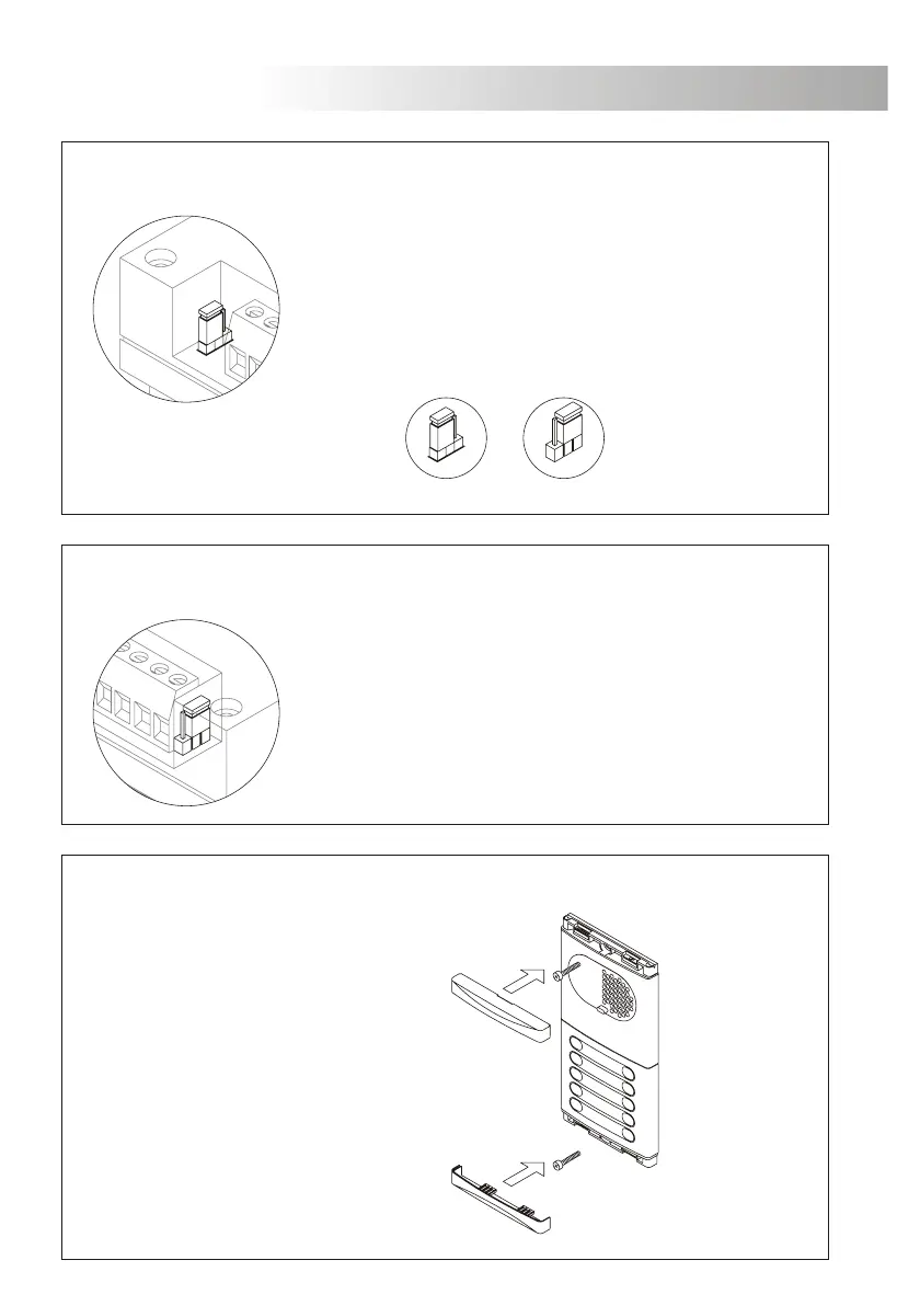
lose the door panel.
C
Fix the door panel by using the supplied
screws.
Finish the door panel assembly by pressing
the closing heads.
lectronic call selection.
E
Electronic call. Buzzer call.
1
2
3
1
2
3
EL551 sound modules for systems with several access doors
have a jumper placed on the right side of the terminal connector.
This jumper allows to select between two different electronic call
types, allowing the user to distinguish which door panel is calling.
all type selection.
C
EL555 sound modules for systems with one access door
have a jumper placed on the left side of the terminal connector.
This jumper allows to select between two different call types:
electronic call (factory default) or buzzer call.
 Loading...