INSTALLATION DIAGRAM
43
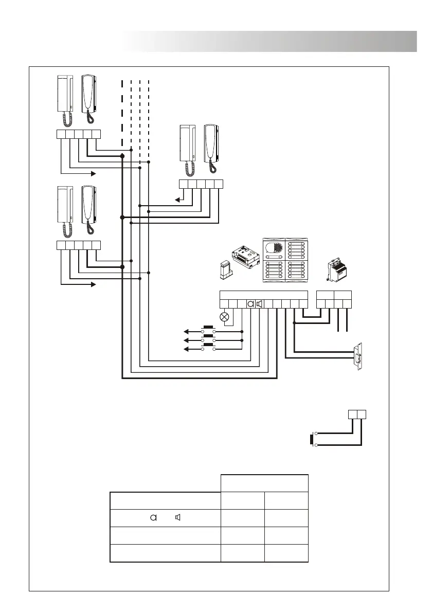
The lock release can be activated at any moment by using an external
push button, that must be connected between '–' and 'P' terminals
of the sound module. This function will allows to exit from the
building being not necessary the use of a key.
P
-
For longer distances than the specified contact with your distributor.
5, , 10, , P, P1 0,25mm² 0,50mm²
0,50mm² 1,00mm²
1,00mm² 2,50mm²
Terminal 100m.
Sections chart
300m.
–, 3, 7, ind
~1, ~2, CV
ne access door.
o
Buzzer call.
CVCPL1 L2
ind. 1
ind. 1
ind. 3
ind. 2
ind. 2
ind. 3
P
CN1
-
~1~2
TF-104
Stadio Plus
SEC
~~
PRI
~~
7
7
10
10
5
5
3
3
P1
P1
7 10 5 3 P1
Main
EL555
1
2
3
INSTALLATION DIAGRAM
44
0, ind, 5, , 10, , P, P1 0,25mm² 0,50mm²
0,50mm² 1,00mm²
1,00mm² 2,50mm²
100m. 300m.
–, 3
~1, ~2, CV
ne access door.
O
Electronic call.
CVCPL1 L2
ind. 1
ind. 1
ind. 3
ind. 2
ind. 2
ind. 3
P
CN1
-
~1~2
TF-104
Stadio Plus
SEC
~~
PRI
~~
0
0
10
10
5
5
3
3
P1
P1
0 10 5 3 P1
Main
P
-
The lock release can be activated at any moment by using an external
push button, that must be connected between '–' and 'P' terminals
of the sound module. This function will allows to exit from the
building being not necessary the use of a key.
For longer distances than the specified contact with your distributor.
Terminal
Sections chart
EL555
1
2
3