10
Manual
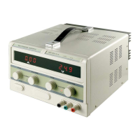
6 Graphic Diagram and Operating Elements:
20325
1 LCD/LED display for output current 7 output socket (black) negative pole
2 LCD/LED display for output voltage 8 ground for the housing
3 LED constant current mode (CC) 9 output socket (red) positive pole
4 ne adjust - output current 10 ne adjust - output voltage
5 coarse adjust - output current 11 coarse adjust - output voltage
6 mains switch 12 LED constant voltage mode (CV)
13 output ON/OFF switch
7 Short-CircuitIdentication:
1. Switch off the power supply.
2. Turn the control dials 4, 5, 10 and 11 to maximum.
3. First switch on the power supply, then the load.
3.2 Ampere is displayed at display 1 and the CC LED ashes on. If 0.0V is displayed at
LCD/LED display 2, load is short-circuited. If another value is shown, the device is
overloaded. Avoid this situation!
8 Installing and Operating:
1. Place the power supply on a safe surface and connect the mains cable to a 220-240V
AC mains socket
2. Connect the load correctly to the DC outputs of the power supply.
3. Switch on the power supply.
4. Adjust the individual current and voltage.
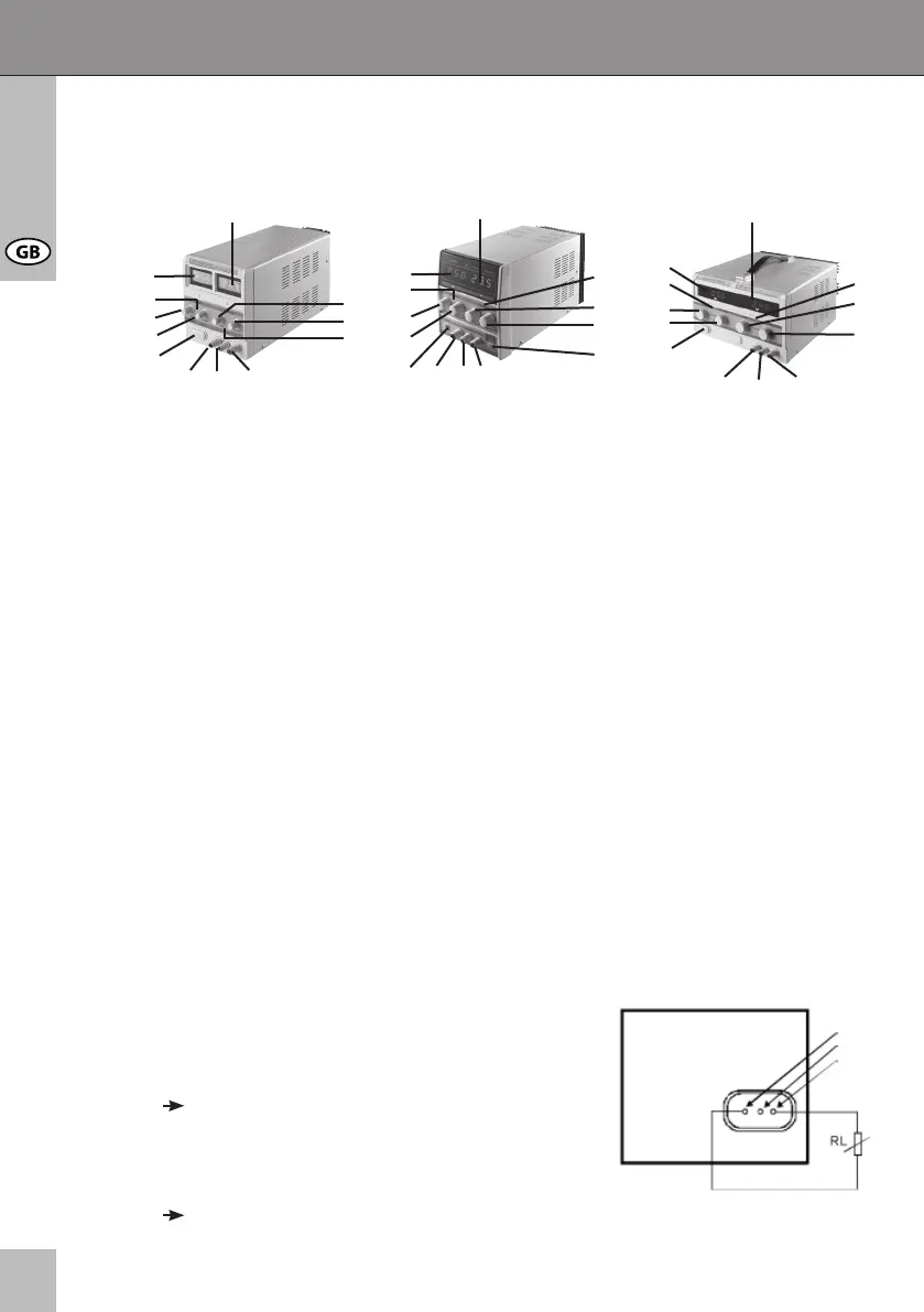
Connecting the Load:
1. Connect the load like shown on the right.
2. Switch on the power supply and the load.
Display 1 shows the output current and display 2
shows the output voltage.
If display 2 shows 3.2A and the CC LED ashes on,
the device is overloaded or there is a short-circuit.
Check the load and all test leads.
1
3
4
5
6
2
7 8 9
10
11
12
1
3
4
5
6
2
7 8 9
12
10
11
13
1
3
4
5
6
2
7 8 9
12
10
11
2032720319
7
8
9