EasyManua.ls Logo

Goodman ASPF426016 - User Manual

Goodman ASPF426016
16 pages
Print Icon
To Next Page IconTo Next Page
Loading...
© 2007 - 2012 Goodman Manufacturing Company, L.P.
5151 San Felipe, Suite 500, Houston, TX 77056
www.goodmanmfg.com - or - www.amana-hac.com
P/N: IO-431A Date: November 2012
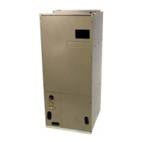
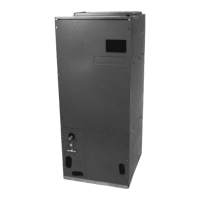
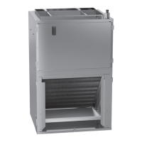
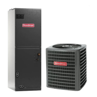
ASPF
AIR HANDLERS
INSTALLATION & OPERATING INSTRUCTIONS
RECOGNIZE THIS SYMBOL AS A SAFETY PRECAUTION.
ATTENTION INSTALLING PERSONNEL
Prior to installation, thoroughly familiarize yourself with this Installation Manual.
Observe all safety warnings. During installation or repair, caution is to be observed.
It is your responsibility to install the product safely and to educate the customer on its safe use.
CONTENTS
Important Safety Instructions............................................. 2
Shipping Inspection ........................................................... 3
Codes & Regulations ........................................................ 3
Replacement Parts............................................................ 3
Pre-Installation Instructions ............................................... 3
Location............................................................................. 3
Ductwork ........................................................................... 3
Return Ductwork.............................................................. 4
Return Air Filters.............................................................. 4
Electric Heat ...................................................................... 4
HKR Installation................................................................. 4
Electrical Supply Wire and MOP ....................................... 4
Building Electrical Service Inspection.............................. 5
Wire Sizing ...................................................................... 5
Maximum Overcurrent Protection (MOP) ........................ 5
Electrical Connections – Supply Voltage ......................... 5
Air Handler Only (Non-Heat Kit Models) ..................... 5
Air Handler With Non-Circuit Breaker Heat Kits.......... 5
Air Handler With Heat Kits
Containing a Circuit Breaker ................................... 5
Low Voltage Connections ........................................... 6
Refrigerant Lines ............................................................... 6
Tubing Preparation .......................................................... 6
Post Brazing .................................................................... 6
Piping Size ...................................................................... 6
Special Instructions ......................................................... 6
Downflow Conversion ....................................................... 7
Horizontal Conversion ....................................................... 7
Condensate Removal........................................................ 8
Achieve 2% Low Leakage Rate ........................................ 9
ASPF Motor....................................................................... 9
CFM Delivery................................................................... 9
Start-Up Procedure ........................................................... 9
Regular Maintenance ........................................................ 9
ASPF Thermostat Connections ....................................... 10
Cooling Unit w/Optional Heat Kits
of 10kW and Below ................................................... 10
Cooling Unit w/Optional Heat Kits
of 15kW and Above
and Room Thermostat w/Two Stages of Heat........... 11
Heat Pump Unit/Optional Heat Kits
of 10kW and Below ................................................... 11
Heat Pump Unit w/Optional Heat Kits
of 15kW and Above................................................... 12
ASPF Wiring Diagram ..................................................... 13
Question and Answer IconNeed help?

Do you have a question about the Goodman ASPF426016 and is the answer not in the manual?

Summary

Important Safety Instructions

High Voltage Warning

Warning about disconnecting power before servicing to prevent injury or death.

Installation by Qualified Personnel

Emphasizes that only qualified individuals should install or repair the unit.

Electrical Power Supply

States the unit is factory-shipped for 208/240/1/60 power and should not be reconfigured.

Electrical Grounding Requirement

Mandates an uninterrupted, unbroken electrical ground for safety.

Carbon Monoxide Hazard

Details risks of CO poisoning in enclosed areas and required ventilation.

Pre-Installation Procedures

Preparation and Tools

Advises reading instructions, gathering tools, and understanding special considerations before installation.

Ductwork System Requirements

Ductwork Sizing and Sealing

Emphasizes proper ductwork sizing, sealing, and avoiding restrictions for optimal performance.

Electric Heat Kit Installation

Approved Heat Kits

States only HKR series heat kits are approved and lists incompatible models.

Electrical Supply Wire and MOP

Copper Conductor Warning

Warns that only copper conductors should be used to prevent fire hazards.

Electrical Service and Wire Sizing

Single-Phase Power Requirement

Confirms unit is for single-phase supply and not three-phase.

Wire Sizing Guide

Guides on selecting wire size based on Minimum Circuit Ampacity (MCA) and voltage drop.

Maximum Overcurrent Protection (MOP)

Protection Device Selection

Mandates NEC/CEC approved overcurrent protection (fuses or HACR breakers) sized appropriately.

Electrical Connections

Supply Voltage Connection Details

Details connecting supply voltage wires using copper conductors and proper strain relief.

Refrigerant Lines Installation

Pressure Handling Warning

Warns that the product is factory-shipped under pressure and requires careful handling.

Downflow Conversion Procedure

Horizontal Conversion Requirements

Horizontal Conversion Steps

Condensate Removal System

Drain Connections and Torque Settings

Describes primary/secondary drain connections, required fittings, and proper torque settings.

Condensate Trap Installation

Mandates a 'P' style trap near the coil for proper drainage, preventing backflow and sewer gases.

Condensate Management Guidelines

ASPF Motor and CFM Control

Start-Up Procedure Checklist

ASPF Thermostat Wiring Overview

Wiring Configuration Overview

Details various configurations for thermostat and outdoor unit connections, mentioning jumper settings for blower speed.

ASPF Thermostat Wiring Diagrams (Cooling & HP 10 kW)

ASPF Thermostat Wiring Diagrams (HP 15 kW+)

ASPF Wiring Diagram Details

High Voltage Wiring Schematics

Details high voltage connections for element rows and transformer terminals.

Low Voltage Wiring Schematics

Explains low voltage wiring, component codes, and color codes for connections.

Filter Replacement and Cleaning

Goodman ASPF426016 Specifications

General IconGeneral
BrandGoodman
ModelASPF426016
CategoryAir Handlers
RefrigerantR-410A
Phase1
Voltage208-230V

Related product manuals