EasyManua.ls Logo

Goodman AVPTC24B14A - User Manual

Goodman AVPTC24B14A
10 pages
Print Icon
To Next Page IconTo Next Page
Loading...
Refer to Service Manual RS6200006 for installation, operation & troubleshooting information.
All safety information must be followed as provided in the Service Manual.
Refer to the appropriate Parts Catalog for part number information.
Models listed on page 3.
TECHNICAL MANUTECHNICAL MANU
TECHNICAL MANU
ALAL
ALAL
AL
RT6121004r2
March 2014
Copyright © 2013-2014 Goodman Manufacturing Company, L.P.
This manual is to be used by qualified, professionally trained HVAC technicians only. Goodman
does not assume any responsibility for property damage or personal injury due to improper
service procedures or services performed by an unqualified person.
AVPTC Air Handlers
Question and Answer IconNeed help?

Do you have a question about the Goodman AVPTC24B14A and is the answer not in the manual?

Summary

TECHNICAL MANUAL

AVPTC Air Handler Introduction

Provides an overview of the AVPTC Air Handler technical manual.

PRODUCT IDENTIFICATION

Model Number Structure and Purpose

Explains the model number's role in identifying components.

Unit Type, Expansion, and Cabinet Details

Covers unit type, expansion device, cabinet finish, and dimensions.

Application, Refrigerant, and Electrical Specs

Details unit applications, refrigerant type, and electrical requirements.

Nominal Capacity Ratings

Lists nominal cooling capacity for different models.

PRODUCT IDENTIFICATION (continued)

Specific AVPTC Model Number Listings

Provides a list of specific model numbers for AVPTC air handlers.

Refrigerant Handling and Safety Warnings

Consolidates critical safety precautions for refrigerant handling.

Installation and Electrical Safety Precautions

Highlights safety for installation, grounding, and non-approved devices.

PRODUCT DESIGN

Installation Environment and Ignition Safety

Covers safety in garages, CO production, and ignition sources.

High Voltage and Electrical Grounding Safety

Reiterates high voltage dangers and proper electrical grounding.

Unit Installation Features and AVPTC Specifics

Discusses installation positions, clearances, attic installations, and AVPTC features.

PRODUCT DIMENSIONS

Dimensional Drawings and Measurements

Shows detailed measurements for unit components and ports.

PRODUCT DIMENSIONS (continued)

Model Dimension Tables

Presents a table of physical dimensions for different AVPTC models.

PRODUCT SPECIFICATIONS

Technical Specifications Table by Model

Lists detailed technical specs including capacity, blower, and electrical data.

BLOWER PERFORMANCE DATA

Speed Selection Dip Switch Settings

Explains how to configure blower speed using dip switches.

Airflow Tables for Cooling & Heat Pump

Provides airflow data for various models and speed taps.

Blower Operation and Airflow Notes

Offers operational notes on airflow settings and system compatibility.

HEAT KIT INFORMATION

Electric Heat Airflow Rates Table

Details airflow rates for various electric heat kits.

Heat Kit Model Compatibility Matrix

Shows which heat kits are compatible with specific models.

WIRING DIAGRAMS

General Unit Wiring Diagram and Notes

Illustrates main electrical connections and important operational notes.

Control Module and Thermostat Wiring

Details connections for the integrated control module and thermostat.

WIRING DIAGRAMS (continued)

3-Phase Heat Kit Wiring Diagram

Shows electrical wiring for units with a 3-phase heat kit.

25 kW Heat Kit Wiring Diagram

Illustrates electrical wiring for units with a 25kW heat kit.

Overview

This document is a technical manual for AVPTC Air Handlers, providing essential information for qualified, professionally trained HVAC technicians. It covers product identification, technical specifications, blower performance data, heat kit information, and wiring diagrams.

Function Description

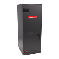
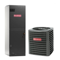
The AVPTC Air Handler is a multi-position, variable-speed air handler designed for use with R-410A refrigerant. It incorporates a variable-speed ECM (Electronically Commutated Motor) blower, making it compatible with heat pumps and variable-capacity cooling applications. The unit is designed to provide heating and cooling for residential and commercial spaces.

Important Technical Specifications

Product Identification

The model number provides detailed information about the unit's configuration:

  • Product Type: A (Air Handler)
  • Expansion Device: F (Flowrater), T (TXV), or C (4-Wire Communicating Ready)
  • Cabinet Finish: U (Unpainted), P (Painted), N (Uncased)
  • Nominal Capacity Range: Available in 2, 2.5, 3, 3.5, 4, and 5 Tons.
    • 24: 2 Tons
    • 30: 2 1/2 Tons
    • 36: 3 Tons
    • 42: 3 1/2 Tons
    • 48: 4 Tons
    • 60: 5 Tons
  • Cabinet Dimensions: B (17.5"), C (21"), D (24.5")
  • Electrical: 1 (208-230V/1ph/60Hz)
  • Refrigerant Charge: 4 (R-410A)
  • Application:
    • C: Ceiling Mount PSC Motor
    • D: Downflow PSC Motor
    • E: Multi-Position Variable Speed Motor
    • R: Multi-Position PSC Motor
    • S: Energy-Efficient Motor: Multi-Position PSC Motor
    • T: Coated Coils
    • V: Variable Speed ECM Motor
    • W: Wall Mount PSC Motor

General Specifications

  • Power Supply: All air handlers use direct drive motors and operate on AC 208-230V, 60 Hz, 1 phase.
  • Clearance: Designed for zero inches (0 inches) clearance, but adequate access for service or replacement must be considered.
  • Leakage Rate: Factory-sealed to achieve a 2% or less leakage rate at 1.0" water gauge external duct static pressure.
  • Electric Heat Kits: Optional 3 kW to 25 kW electric heat kits are available for field installation.

Nominal Ratings (Examples for various models)

  • Cooling (Btu/h): Ranges from 24,000 to 60,000.
  • CFM (High range): Ranges from 1100/600 to 2000/1600.
  • Blower Diameter: 10 5/8" or 11 5/8".
  • Blower Width: 6", 8", or 10 5/8".
  • Coil Drain Connect FPT: 3/4".
  • Refrigerant Line Connection Size:
    • Liquid: 3/8"
    • Suction: 3/4", 7/8"
  • Electric Heat Capacity (kW): Various options from 3 kW to 25 kW.
  • Min Circuit Ampacity: Ranges from 4.9/4.9 to 8.6/8.6.
  • Max. Overcurrent Device (amps): 15/15.
  • Minimum VAC: 197.
  • Maximum VAC: 253.
  • Blower Motor FLA: Ranges from 3.9 to 6.9.
  • Blower Motor HP: 1/2, 3/4, or 1.
  • Ship Weight (lbs): Ranges from 100 to 167.

Blower Performance Data

The manual provides detailed tables for speed selection dip switches and cooling/heat pump airflow.

  • Speed Selection Dip Switches: Configurable for Cool Selection, Adjust Selection, Profile Selection, and Continuous Fan Speed.
    • To set Airflow: Dip switches S1 and S2 for High Stage Cooling Airflow, S9-S11 for electric heater size, and S3-S4 for airflow adjustment (Trim Enable Switch S8).
    • To Set Comfort mode: Dip switches S5 and S6 for Comfort Mode Profile.
    • Dehumidification: Dip switch S7 enables/disables dehumidification, reducing cooling airflow to 85% of nominal value.
    • Continuous Fan Speed: Dip switches S12 and S13 select continuous fan speeds (25%, 50%, 75%, 100%).
  • Cooling/Heat Pump Airflow Table: Provides Low and High stage CFM values for different models and speed taps (A, B, C, D).

Heat Kit Information

Detailed tables show electric heat airflow for various heater kW ratings and models, along with compatibility information for different outdoor unit tonnages.

  • Htr kW: 3, 5, 6, 8, 10, 15, 19, 20, 21, 25.
  • Airflow Requirements: Specific CFM speed tap settings are required for different heater kits and outdoor unit match-ups to ensure proper operation and prevent issues. For example, a 2-ton outdoor unit match-up should not exceed 10 kW heater kit, with airflow set to 850 cfm speed tap of ON-ON-ON.

Usage Features

  • Multi-Position Installation: Can be installed in vertical or right horizontal positions without modification. Horizontal left and downflow positions require product modification.
  • Variable Speed ECM Motor: Provides efficient and adaptable airflow for various heating and cooling demands.
  • Communicating System Compatibility: Designed to work with communicating thermostats and outdoor units for enhanced control and efficiency.
  • Downflow Kit: Required for downflow installations in unconditioned spaces to prevent sweating on the vertical drain pan.
  • Secondary Drain Pan: Recommended for attic installations to manage potential leaks or main drain blockages.
  • Safety Features: Includes warnings for high voltage, proper grounding, and the use of approved devices.

Maintenance Features

  • Service Manual Reference: Technicians are directed to Service Manual RS6200006 for installation, operation, and troubleshooting information.
  • Parts Catalog Reference: Technicians should refer to the appropriate Parts Catalog for part number information.
  • Diagnostic Display: A 7-segment diagnostic display, CFM LED, and RX LED provide status and fault information.
  • Fault Recall: The unit can recall the last 6 faults for diagnostic purposes.
  • Network Status: Red and green LEDs indicate network status and traffic for communicating systems.
  • Condensate Alarm Switch (CAS): Available for communicating mode setups to detect condensate issues.
  • Wiring Diagrams: Detailed diagrams are provided for 3-phase and 25kW heat kits, illustrating electrical connections and components.
  • Replacement Parts: Emphasizes the use of manufacturer-specified replacement parts and wiring materials with appropriate temperature ratings (at least 105°C).

Goodman AVPTC24B14A Specifications

General IconGeneral
BrandGoodman
ModelAVPTC24B14A
CategoryAir Handlers
LanguageEnglish

Related product manuals