11
12RC
12RC
CTK0*AA
Thermostat
CT Compatible Air
Handler/Furnace/Modular
Blower Integrated
Control Module
CT Compatible
AC/HP Integrated
Control Module
40VA Transformer (included in
CTK0*AA kit)
208/230 VAC
24 VAC
12RC
System Wiring using Two-Wires between Furnace and AC/HP
and Four-Wires between Furnace and Thermostat
COMFORTNET™ SYSTEM A DVANCED F EATURES
The ComfortNet system permits access to additional system
information, advanced setup features, and advanced diag-
nostic/troubleshooting features. These advanced features
are organized into a menu structure. The menus are ac-
cessed and navigated as described below.
ACCESSING AND NAVIGATING THE ADVANCED FEATURES
MENUS
The advanced system features are accessed using the
ComfortNet™ thermostat. These advanced features are ac-
cessed as follows:
• On the CT thermostat Home Screen Display, touch
the Menu key to display additional key choices.
• Touch and hold the Installer Config key for
approximately 3 seconds to enter the Thermostat
Options Configuration menu.
• Touch and hold the Installer Config key again for
approximately 3 seconds to enter the Advanced
Installer Configuration menu.
Clean Display
Installer
Config
Set Time
Set
Schedu le
Run
Schedule
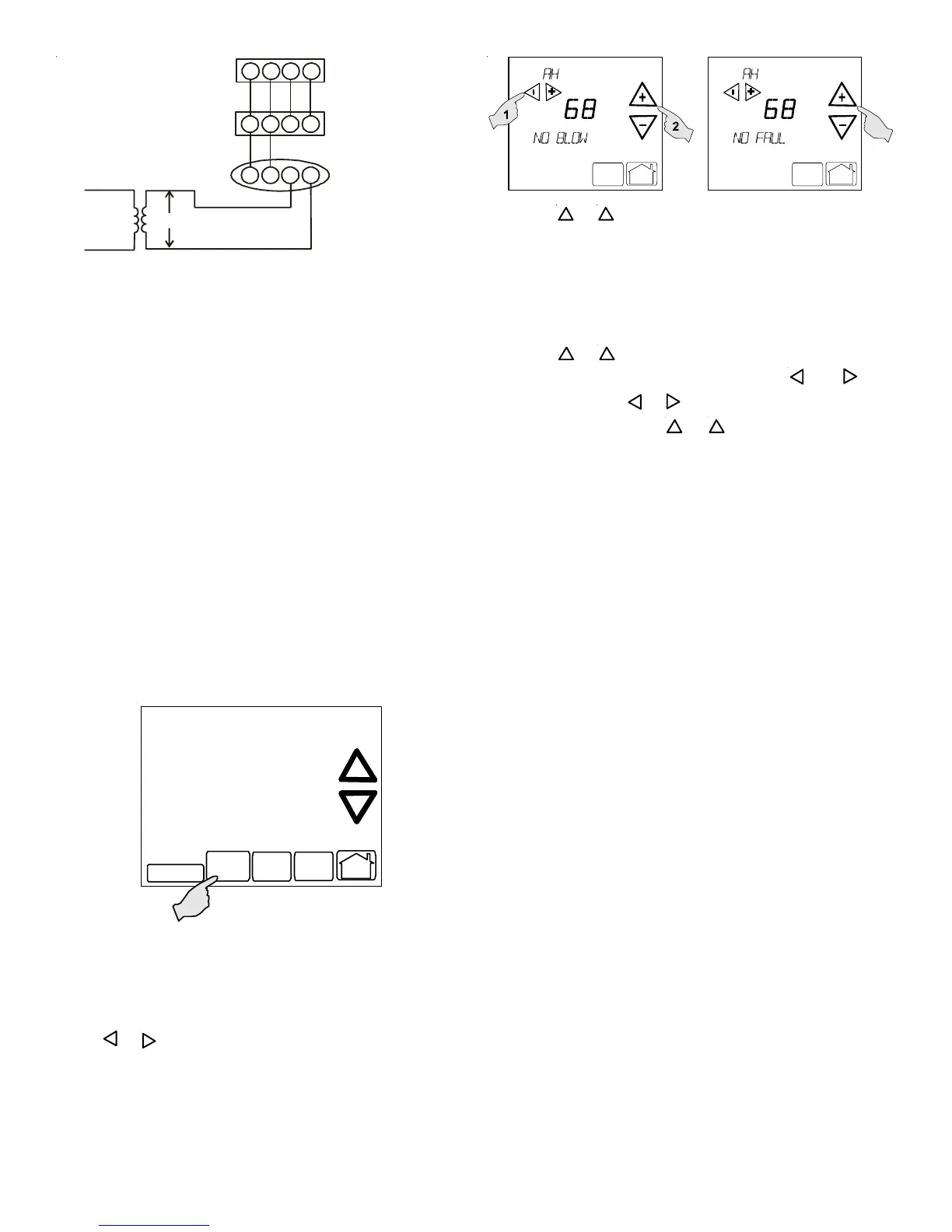
Upon entering the advanced menus, the Advanced Fault Menu
is displayed. The display will change to the Fault Screen and
indicate any faults that may be present in the indoor or outdoor
equipment. If a fault is present, the Fault Screen will show the
equipment and an error code with a description of the fault.
Touch
_
or
+
keys to view the fault status of any remaining
equipment. The text “NO FAULTS” will be scrolled if no errors
are present.
Menu
Run
Schedule
Call for Service
Advanced
Menu
Run
Schedule
Call for Service
Advanced
Touch the
+
or
_
to step through the list of installed equip-
ment, including the thermostat. Touch the Installer Config
key to enter the submenus for the equipment displayed. The
text “WORKING” will be displayed in the scrolling display
area while the data is being retrieved. The first sub-menu is
then displayed. See tables below for listing of furnace sub-
menus.
Touch the
+
or
_
to step through the list of submenus and
view settings. If a setting can be adjusted,
_
and
+
keys
will appear. Use the
_
or
+
keys to adjust the setting to the
desired value. Touch the
+
or
_
to step to the next item.
“WORKING” will appear as the settings are being updated.
“DONE” will appear to indicate the change was accepted. If
the change is not accepted, the display will show “FAIL” then
revert to the Fault Screen.
Some parameters being displayed switch between the item
name and the item value. Touch the Hold key to momen-
tarily stop the display from switching.
To exit an equipment submenu and revert back to the equip-
ment menus, touch the Menu key. Touch Menu again to re-
vert back to the Thermostat Options Menu. Touch the Run
Schedule key to step out of all menus and back to the CT
thermostat Home Screen Display.
If this heat pump is installed with a CT compatible air handler/
modular blower, the system is recognized as a heat pump
system. The electric heat disabled temperature and heat pump
disabled temperature must be set via the thermostat advanced
menu. Navigate to the THERMOSTAT menu. Press the IN-
STALLER CONFIG key. Navigate to the SETUP menu and
press the INSTALLER CONFIG button. Navigate to AUX HT
LOCKOUT. Adjust the electric heat disabled temperature to
the desired setting using the back/forward arrows. Navigate to
HP BAL PNT. Adjust the heat pump disabled temperature to
the desired setting using the back/forward arrows.
DIAGNOSTICS
Accessing the air conditioner/heat pump’s diagnostics menu
provides ready access to the last six faults detected by the air
conditioner/heat pump. Faults are stored most recent to least
recent. Any consecutively repeated fault is stored a maximum
of three times. Example: The power supply to the air condi-
tioner/heat pump is continuously below 187 VAC. The control
will only store this fault the first three consecutive times the
fault occurs. Navigate to the diagnostics menu as described
above in Accessing and Navigating the Advanced Features
Menus.
NOTE: It is highly recommended that the fault history be cleared
when performing maintenance or servicing the heat pump.