Do you have a question about the Goodman GSX Series and is the answer not in the manual?
Covers high voltage, qualified installers, child supervision, and use of certified devices.
Includes verifying contents and adhering to installation codes and regulations.
Details on ordering replacement parts.
Read instructions, gather tools, and ensure all supplies are ready before installation.
Covers compressor handling, pump down, time delay, and safe unbrazing.
Outdoor unit inspection, cleaning, and air filter servicing are recommended.
Ensure unrestricted airflow, service access, and consider noise impact on occupied spaces.
Install on a solid, level foundation with good drainage, considering elevation for winter conditions.
Match power supply, follow codes, ensure grounding, and insulate suction lines.
Includes precautions for brazing, line preparation, and nitrogen sweeping.
Pressure test the system using nitrogen and soapy water to detect leaks.
Evacuate the system to 250 microns or less and hold vacuum to check for leaks.
Open valves correctly, purge lines, and weigh in the calculated refrigerant charge.
Set thermostat for cooling, check fan operation, and allow system stabilization.
Determine indoor airflow and heating capacity using temperature rise or airflow instruments.
Measure return and supply air temperatures accurately to determine temperature rise.
Use Table I to determine system power output based on airflow and temperature rise.
Charge system by weight, adjusting for line size and length as per tables.
Connect gauges, measure suction line temperature, and determine superheat.
Use Table IV to check system superheat against ambient and return air temperatures.
Follow startup checklist for heating mode, including thermostat settings and fan operation.
Check supplementary heat, defrost cycle, air distribution, and vibrations.
Brief descriptions of Contactor, Crankcase Heater, Condenser Motor, Compressor, and Defrost Control.
Explains how heat pump functions in cooling and heating modes, including refrigerant flow.
Describes how defrost accumulation is managed by reversing the refrigerant flow.
Addresses dirty filters, outside air intrusion, undercharge, defrost thermostat, and reversing valve faults.
Tips for efficient heat pump use, thermostat settings, and uniform room temperature.
Provides tables for selecting correct refrigerant line diameters based on length and tonnage.
Offers capacity multipliers for different suction line sizes and tubing lengths.
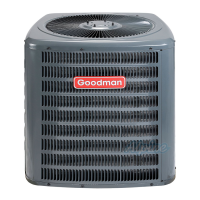
This document provides installation and operation instructions for a split system outdoor unit, specifically the 50HZ R410A GSX and GSZ series. It emphasizes safety, proper installation techniques, and maintenance procedures to ensure optimal performance and longevity of the unit.
The manual begins by highlighting the importance of safety, using symbols and labels to indicate potential hazards. It stresses that both the owner and installer are responsible for reading and complying with all safety information. Failure to do so can lead to personal injury, property damage, or product damage. A prominent warning advises disconnecting all power before servicing due to multiple power sources, emphasizing that failure to do so can result in property damage, personal injury, or death. Another warning states that installation and repair should only be performed by "entry level technicians" as specified by National Codes, as improper handling can lead to product damage or failure. The document also includes a warning about the appliance not being used by children or persons with reduced physical, sensory, or mental capabilities without supervision or instruction, and advises supervising children to prevent them from playing with the appliance. A final warning in this section cautions against connecting or using any device not design-certified by Goodman for use with this unit, as this can cause serious property damage, personal injury, reduced unit performance, and/or hazardous conditions.
Before installation, users are instructed to thoroughly familiarize themselves with the manual, observe all safety warnings, and exercise caution during installation or repair. The installing personnel are responsible for safe installation and educating the customer on safe use.
The shipping inspection section advises keeping the unit upright to prevent equipment damage and notes that shipping damage is the carrier's responsibility. It also instructs installers to verify the model number, specifications, electrical characteristics, and accessories before installation, as claims for transportation damage or incorrectly shipped units will not be accepted by the distributor or manufacturer.
Regarding codes and regulations, the product is designed to comply with national codes, and installation must adhere to these and local codes/regulations. The manufacturer disclaims responsibility for equipment installed in violation of any codes. Rated performance is achieved after 72 hours of operation at the specified airflow. Specification sheets for various models can be found on the Goodman and Amana websites. Electrical disconnection must be incorporated in fixed wiring if the equipment lacks a supply cord or plug, ensuring full disconnection under overvoltage category III conditions. The handling of refrigerants may be subject to regulations, and failure to comply can harm the environment and lead to substantial fines. Users with questions are advised to contact their local regulatory agency.
For replacement parts, users should provide the complete product model and serial numbers when reporting shortages or damages, or ordering parts. These parts are available through contractors or local distributors.
The pre-installation instructions emphasize reading all instructions carefully, understanding each step, and accounting for special considerations. Installers should assemble all necessary tools, hardware, and supplies before starting.
A dedicated section covers installation and operating information for units with scroll compressors. A caution warns that dome temperatures can be hot when handling scroll compressors. This section provides crucial information for installing these units:
An important message to the owner advises reading and keeping the instructions for future reference, particularly the maintenance section. It explains that the heat pump operates like a summer air conditioning unit in cooling mode. Users should let the thermostat control the system and avoid tampering with it. If the conditioned area temperature is not suitable, the thermostat setting should be adjusted one degree at a time. The manual notes that a heat pump heats a building less rapidly than a furnace and may take a day or two to "pull down" a cold, moist house initially or after prolonged shutdowns.
It is recommended to inspect the outdoor unit and clean it if necessary each cooling season. Special attention should be given to the air inlet side of the outdoor coil to ensure it is free from leaves, grass, etc., which can restrict airflow, reduce system capacity, increase operating pressures, and raise operating costs. If the unit is near a grassy area, lawn mowers should be routed to direct discharge away from the unit. Air filters must be installed upstream of the indoor coil and inspected, replaced, or cleaned at least monthly. Disposable filters should be kept in adequate supply, and equipment should never be operated without filters. Permanent filters can be vacuumed or washed but must be thoroughly dry before reinstallation. Filters are often marked to indicate airflow direction, which must be carefully noted during installation; dirty filters should never be turned to allow airflow in the opposite direction.
The blower and motor bearings are permanently lubricated and do not require additional lubrication. Some outdoor units have factory-wired heaters that operate when main power is on. Before starting equipment after prolonged shutdowns or initial startup, circuits should be closed for at least 24 hours.
The manufacturer intends this equipment to be used only with indicated components. A warning reiterates not to connect or use any device not design-certified by Goodman, as this can cause serious property damage, personal injury, reduced unit performance, and/or hazardous conditions. Users are directed to reference specification sheets for performance values and approved system matches.
The outdoor unit, accessible to the public, should be located to ensure unrestricted airflow through the coil. For adequate service access, the service side should be at least 30.5 cm from any wall or obstruction. The impact of outdoor fan noise on conditioned and adjacent occupied spaces should be considered, and the unit should be placed so that discharge does not blow towards windows less than 7.6 m away.
The outdoor unit should be placed on a solid, level foundation, preferably a concrete slab at least 10.2 cm thick, above ground level, and surrounded by a graveled area for good drainage. The slab should not adjoin the building to prevent sound and vibration transmission. For rooftop installations, steel or treated wood beams should be used as unit support.
Heat pumps require special location consideration in areas with heavy snow or prolonged subfreezing temperatures. Unit bases are cutout under the outdoor coil for frost accumulation drainage. Units must be situated to permit free, unobstructed drainage of defrost water and ice. A minimum 7.6 cm clearance under the outdoor coil is required in milder climates. In severe weather, units should be elevated for unobstructed drainage and airflow.
Regarding elevation, if the outdoor unit is above the air handler, the maximum suction line lift should not exceed 21.3 m. If the air handler is above the condensing unit, the maximum liquid line lift should not exceed 15.2 m. An inverted loop in the suction line near the evaporator connection is required when the evaporator coil is above the condensing unit, with the top of the loop slightly higher than the top of the coil. An oil trap in the suction line at the evaporator is not required when the condensing unit is above the evaporator coil, unless the condensing unit is over 80 feet above the evaporator. Users are directed to refer to the latest revision of long line set guidelines TP-107.
Supply power, voltage, frequency, and phase must match the unit nameplate. All wiring must be checked against manufacturer's diagrams and connected according to the National Electric Code and local codes. Equipment must be adequately grounded. The manufacturer is not responsible for damage caused by using larger than recommended protective devices. The equipment has been started at minimum rated voltage and checked for satisfactory operation; users should not operate the unit if available voltage is outside the minimum and maximum shown on the nameplate.
Insulation of at least 1.3 cm wall thickness should be used on the suction line to prevent condensation during cooling and heat loss during heating. The insulation should cover the entire length of the installed line. The end of the tubing over which insulation is slipped should be covered to prevent foreign material from entering the tubing. Outdoor units have two service valves, which are "as shipped" in the front-seated or "closed" position.
The indoor coil is pressurized; the copper cap must be punctured to allow gradual pressure escape before unsweating. Tubing should be coupled to the indoor unit immediately to minimize moisture exposure.
To prevent overheating service valves or expansion devices during brazing, components should be wrapped with a wet rag or thermal heat trap compound. Schrader valves must be removed from service valves before brazing. A brazing alloy with a minimum 2% silver content should be used, and flux should not be used. Torch heat should be appropriate for the tube size to avoid melting the tube. A heat shield is recommended to prevent burning the serial plate or unit finish. After brazing, joints should be quenched with water or a wet cloth to prevent service valve overheating. The filter drier paint finish must be intact; if burned or chipped, it should be repainted or treated with a rust preventative, especially for suction line filter driers that are continually wet during operation. Before brazing, the indoor piston size should be verified using the piston kit chart.
The system should be pressure tested to approximately 100 PSI with dry nitrogen. Soapy water can be used to locate leaks. For leak detectors, the system should be charged to 10 psi with refrigerant, then topped off with nitrogen to working pressure. Leaks must be repaired, and the pressure test repeated. If no leaks are found, proceed to system evacuation. Scroll compressors should never be used to evacuate or pump down a heat pump or air conditioning system.
When opening valves with retainers, open each valve only until the top of the stem is 1/8" from the retainer. Do not apply pressure to the retainer to avoid refrigerant loss. For valves without retainers, remove the service valve cap, insert a hex wrench, and back out the stem counterclockwise until it contacts the rolled lip of the valve body. These are not back-seating valves. Open the suction service valve first to prevent oil from being drawn into the indoor coil TXV. After refrigerant charge has bled into the system, open the liquid service valve. The service valve cap is the secondary seal and must be properly tightened (finger-tight plus 1/6 turn, or to specifications: 3/8" valve to 5-10 in-lbs, 5/8" and 3/4" valves to 5-20 in-lbs, 7/8" valve to 5-20 in-lbs). Do not introduce liquid refrigerant from the cylinder into the compressor crankcase, as this can damage the compressor.
Field variations can affect operating temperature and pressure readings. Goodman Heat Pump Systems use fixed orifice refrigerant control devices.
Before checking the system's charge, verify sufficient airflow across the indoor coil and operating capacity. Airflow Test Instruments: Various instruments like Barometers, Volume-Aire Air Balancers, Anemometers, and Velometers can be used. Follow manufacturer's instructions. Airflow Determination - Indoor Coil: The heat pump system is designed for optimum performance with airflow across the indoor coil of approximately 190 L/s per TON (e.g., a 2 TON system should have 380 L/s). Temperature Rise Method: For systems with electric resistance heat as backup, indoor airflow can be determined by the formula: Air Flow (L/s) = (828.3 x Input Power (kW)) / Temperature Rise (°C), where Input Power (kW) = (measured input voltage (Volt) x current (Amp)) / 1000. For example, with input voltage 230 Volt, current 35 amps, and temperature rise 12°C, airflow = 556 L/s. The compressor circuit (outdoor unit) must be off to ensure temperature rise is due only to electric heat.
The procedure for determining temperature rise across the indoor section:
The temperature rise method can determine heating capacity in heat pump "only" mode. Results should be within 10% of data in specification sheets. When using this procedure, ensure the indoor section's backup heat source is de-energized.
A warning emphasizes safe handling of refrigerants to avoid injury, explosion, or death. Cooling Cycle: The system is properly charged by weighing in the refrigerant amount specified on the outdoor unit nameplate, with adjustments for line size, length, and other system components. Systems with More Than 7.6 Meters of Refrigerant Line Refrigerant Allowance: Systems with interconnecting refrigerant lines longer than 7.6 m require an additional R410A charge allowance per Table II. When indoor and outdoor sections are separated by more than 7.6 meters, note maximum elevation separation limitations from the LOCATION section.
Weighing In Charge: Similar to cooling mode, proper charging is by weight, with adjustments for line size, length, and other system components.
Begin with power off at all disconnects.
Power to the circuit board is controlled by a temperature sensor clamped to a return bend on the outdoor coil. Timing periods of 30, 60, or 90 minutes can be selected by connecting a jumper wire. Time accumulation starts when the sensor closes (approximately -2.2°C) and the wall thermostat calls for heat. At the end of the timing period, a defrost cycle initiates if the sensor remains closed. The defrost cycle terminates when the sensor opens (approximately 18.3°C). If not terminated by sensor temperature, a 10-minute override interrupts the defrost period.
A. Run unit in heat mode. B. Check unit for proper charge. Note: Frost bands indicate low refrigerant charge. C. Shut off power to unit. D. Disconnect outdoor fan by removing the purple lead from "DF2" on defrost control. E. Restart unit and allow frost to accumulate. F. After a few minutes, the defrost thermostat should close. Verify 24 volts between "DFT" and "C" on the board. If temperature at the thermostat is less than -2.2°C and the thermostat is open, replace it. G. When the defrost thermostat has closed, short the "test" pins on the board until the reversing valve shifts, indicating defrost. This can take up to 21 seconds depending on the timing period. The short must be removed instantly after defrost initiation, or the defrost period will only last 2.3 seconds. H. After defrost termination, check the defrost thermostat for 24 volts between "DFT" and "C". The reading should indicate 0 volts (open sensor). I. Shut off power to unit. J. Replace outdoor fan motor lead and turn on power.
The heat pump operates like a summer air conditioning unit in cooling mode. Charts and data for summer air conditioning apply to the heat pump in cooling mode. In heating mode, "condenser" becomes "evaporator," "evaporator" becomes "condenser," and "cooling" becomes "heating."
In heating mode, the reversing valve redirects refrigerant flow. Hot discharge vapor from the compressor goes to the inside coil (evaporator in cooling mode) where heat is removed and vapor condenses to liquid. It then passes through a capillary tube or expansion valve to the outside coil (condenser in cooling mode) where liquid evaporates, and vapor goes to the compressor. The solenoid valve moves the pilot valve, putting suction pressure on one side of the reversing valve and discharge pressure on the other, causing the piston to slide and reverse refrigerant flow.
The manual includes schematic figures showing the heat pump in cooling and heating cycles. In addition to a reversing valve, a heat pump has an expansion device and check valve for the inside coil, and similar equipment for the outside coil, along with a defrost control system. The expansion device functions similarly in both heating and cooling cycles. Check valves are needed due to reverse refrigerant flow.
In heating mode, the outdoor coil functions as an evaporator. Refrigerant temperature in the outdoor coil must be below outdoor air temperature to extract heat. A greater temperature difference means greater heating capacity. It is good practice to provide supplementary heat for installations where temperatures drop below 7.2°C, and sufficient supplementary heat to handle heating requirements if the heat pump fails (e.g., compressor failure, refrigerant leak).
Since liquid refrigerant temperature in the outdoor coil is generally below freezing in heating mode, frost forms. The system reverses flow to the cooling cycle, providing hot gas to the outdoor coil to melt frost. The outdoor fan stops to hasten temperature rise, and the indoor blower continues to run with supplementary heaters energized.
This information is for qualified service agencies only.
A. Dirty Filters or Inadequate Air Volume Through Indoor Coil: In heating mode, the indoor coil functions as a condenser. Clean filters and sufficient airflow are essential to prevent excessive discharge pressure and high pressure cut-out. B. Outside Air into Return Duct: Cold outside air introduced into the return duct near the indoor coil can reduce air temperature below 18.3°C, causing low discharge pressure, low suction pressure, excessive defrost cycling, and false defrosting. C. Undercharge: Undercharge in heating mode causes low discharge pressure, low suction pressure, and frost accumulation on the lower part of the outdoor coil. D. Poor "Terminating" Defrost Thermostat Contact: The defrost thermostat must have good thermal contact on the return bend to quickly terminate the defrost cycle and prevent high discharge pressure cut-out. E. Malfunctioning Reversing Valve: 1. Solenoid Not Energized: Check by touching the nut holding the solenoid cover with a screwdriver; if it magnetically holds the screwdriver in cooling, the solenoid is energized. 2. No Voltage to Solenoid: Check voltage and wiring circuit. 3. Valve Will Not Shift: a. Undercharged: Check for leaks. b. Valve Body Damaged: Replace valve. c. Unit Properly Charged: In heating mode, raise discharge pressure by restricting airflow through the indoor coil. If the valve doesn't shift, tap it lightly on both ends with a screwdriver handle (do not tap the valve body). In cooling mode, raise discharge pressure by restricting airflow through the outdoor coil. If the valve still doesn't shift after these attempts, cut the unit off, wait for discharge and suction pressure to equalize, and repeat. If it still doesn't shift, replace it.
Your heat pump will provide years of comfort. This section introduces you to the operation of your new heating and air conditioning system and its characteristics. A heat pump removes heat from outdoor air and "pumps" it indoors. As outdoor air gets colder, it's harder for the heat pump to remove heat, so the air from registers will gradually feel less warm, though it still warms your home except in extreme weather.
When the outdoor temperature drops too low for the heat pump alone, electric heaters automatically activate. This is normal, and the unit may run continuously during severe cold spells. To maximize economic benefits, minimize electric heater operation. Heaters are controlled by the thermostat and activate about two degrees below the thermostat setting. Moving the thermostat up two degrees energizes heaters in addition to the heat pump. For economical operation, set the thermostat to the desired temperature and leave it there throughout the heating season. Setting the thermostat back at night is not recommended, as the heat pump will work harder in the morning, and electric heaters will energize, which is uneconomical. A heat pump is most economical when maintaining a desired temperature.
Under normal operation, air from registers may feel less warm than from a gas or oil furnace. This is normal; the heat pump supplies larger quantities of air at a lower temperature, resulting in more uniform room temperature and eliminating hot areas. Heated air generally ranges from 32.3°C to 37.8°C, which is ample to heat your home.
Delivering large quantities of air is important. Restricted airflow leads to high operating costs, poor heating, and potential equipment malfunctions or damage. Closed registers and dirty filters are primary causes of restricted airflow. All registers, supply, and return, should be open and not blocked by carpet or furniture. Filters must be inspected at least monthly and cleaned or changed if necessary. The manual recommends contacting your installing dealer for information and yearly inspections by a qualified service technician.
| Refrigerant | R-410A |
|---|---|
| Stages | Single |
| SEER Rating | 13-16 |
| Cooling Capacity (BTU/h) | 18, 000 - 60, 000 BTU/h |
| Compressor Type | Single-Stage |
| Sound Level (dB) | 72-74 |
| Warranty | 10-year limited parts warranty |