Do you have a question about the Goodman TSTATG1100-2 and is the answer not in the manual?
Explains the purpose and importance of the thermal insulating sheet.
Wiring diagram for a 4-wire, single-stage cooling and heating system.
Specific wiring for 4-wire heat pumps with O reversing valve.
Specific wiring for 4-wire heat pumps with B reversing valve.
Wiring diagram for a 3-wire, single-stage heating system.
Wiring diagram for a 2-wire, single-stage gas heat system.
Wiring diagram for dual transformer, 5-wire systems.
Explains output signals based on jumper settings and demand.
Explains output signals for electric heating and cooling modes.
Explains output signals for heat pump operation with O valve.
Explains output signals for heat pump operation with B valve.
Troubleshooting steps when the air conditioning system does not engage.
Troubleshooting steps when the fan does not operate as expected.
Troubleshooting steps when the heating system does not engage.
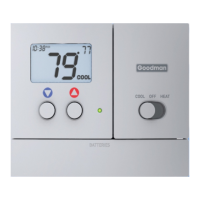
| Type | Non-Programmable |
|---|---|
| Programmability | Non-Programmable |
| Stages | 1 Heat/1 Cool |
| Voltage | 24V AC |
| Temperature Adjustment | 1°F increments |
| Fan Control | Auto/On |
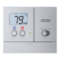
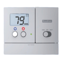
| System Switch | Heat/Off/Cool |
| Wire Terminals | R, C, W, Y, G |
| Backlight | No |
| Display | LCD |
| Compatibility | Single Stage Heating and Cooling Systems |
| Mounting | Wall |
| Power Method | Hardwired |
| Control | Manual |