OM−02806
0 SERIES
MAINTENANCE & REPAIR PAGE E − 9
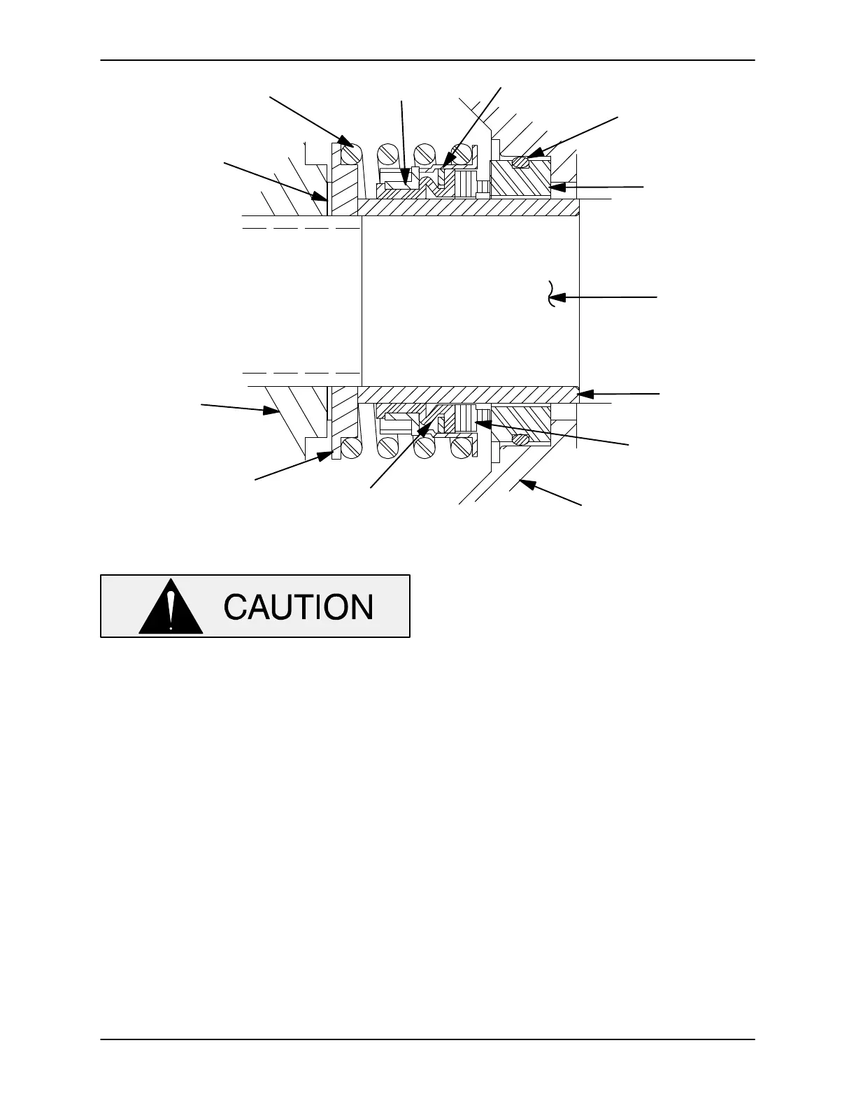
O-RING
STATIONARY
SEAT
IMPELLER
SHAFT
SHAFT
SLEEVE
SEAL PLATE
BELLOWS
SPRING
CENTERING
WASHER
IMPELLER
IMPELLER
ADJUSTING
SHIMS
SPRING DRIVE BAND
RETAINER
ROTATING
ELEMENT
Figure 4. 25271−207 Seal Assembly
This seal is not designed for operation at
temperatures above 160_F (71_C). Do not
use at higher operating temperatures.
Position the seal plate (6) on a flat surface with the
impeller side facing up. Subassemble the O-ring
into the stationary seat and lubricate it with light oil.
Position the stationary seat in the seal plate with the
sealing face up, and use even thumb pressure to
press the stationary seat into the seal plate until ful-
ly seated in the seal plate bore.
After installation, wipe the seal face in a concentric
pattern with a clean, lint-free cloth to remove any
fingerprints.
Position the seal plate and stationary seat over the
shaft and secure it to the intermediate (39) with the
hardware (12 and 13). Be careful not to damage
the stationary element on the shaft threads.
Lubricate the seal sleeve (24) with a small amount
of light oil and slide the rotating subassembly (con-
sisting of rotating element, bellows and retainer),
onto the sleeve until the rotating element is just
flush with the undercut end of the sleeve.
Slide the shaft sleeve and subassembled rotating
portion of the seal onto the shaft until the seal faces
contact. Continue to push the sleeve through the
seal until the undercut end seats against the shaft
shoulder.
Install the seal spring and spring centering washer
(25).
Impeller Installation
Inspect the impeller and replace it if cracked or
badly worn.
For maximum pump efficiency, the impeller must
be centered within the volute scroll.
To verify impeller positioning, measure the pump
casing and impeller as shown in Figure 5. Use
these measurements to calculate the required im-
peller location (dimension E). Add or remove im-


 To Next Page