0 SERIESOM−02806
MAINTENANCE & REPAIRPAGE E − 10
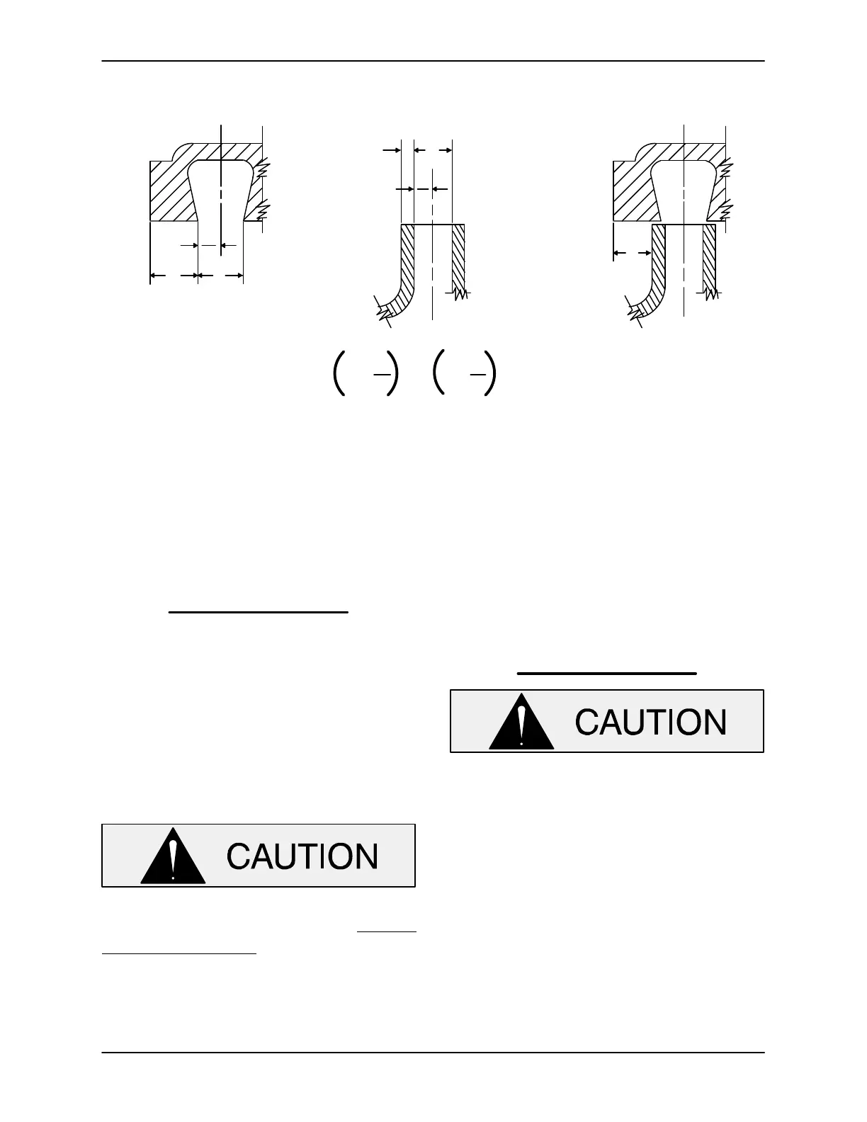
peller adjusting shims until dimension E is ob-
tained.
D
B
2
AB
2
CD
E
Step 2Step 1 Step 3
A
+
B
2
C
+
D
2
E
=
−
Figure 5. Centering Impeller Within Volute Scroll
Install the correct thickness of impeller adjusting
shims (23) and screw the impeller onto the shaft
until tight.
NOTE
After the impeller has been properly positioned,
check for free rotation. Correct any scraping or
binding before further reassembly.
Securing Pump To Engine
Install the shaft key (36) in the shaft keyway. Posi-
tion the tapered bushing (37) on the shaft with the
shoulder on the bushing toward the intermediate.
Align the keyway in the tapered bushing with the
shaft key and slide the bushing onto the shaft until
the shoulder is 1/16 inch from the intermediate.
This dimension is critical.
Make certain that the tapered bushing (36)
is mounted as shown in Figure 6. This di-
mension is critical. The shoulder on the
bushing must be positioned 1/16 inch
away from the face of the intermediate.
This will allow the two portions of the cou-
pling to fully engage when the intermediate
is secured to the engine bellhousing, with-
out pre-loading the bearings.
Position the flexible portion of coupling assembly
on the shaft as shown in Figure 1.
NOTE
The flexible portion of the coupling must be proper-
ly positioned on the shaft. The heads of the caps-
crews in the center of the coupling must be posi-
tioned toward the drive end of the shaft.
If the coupling is not properly positioned
on the shaft, the coupling parts may not ful-
ly engage, or a pre-load condition can
cause premature bearing failure.
Rotate the flexible portion of the coupling until the
holes for the capscrews (32) align with the tapped
holes in the tapered bushing, and install the hard-
ware (32 and 33).
Tighten the capscrews (32) in an alternating se-
quence until the coupling is fully seated on the ta-
pered bushing. Make sure the capscrews do not
protrude through the back of the tapered bushing.
Torque the capscrews to 9 ft. lbs. (108 in. lbs.).


 To Next Page