OM−02806
0 SERIES
MAINTENANCE & REPAIR PAGE E − 11
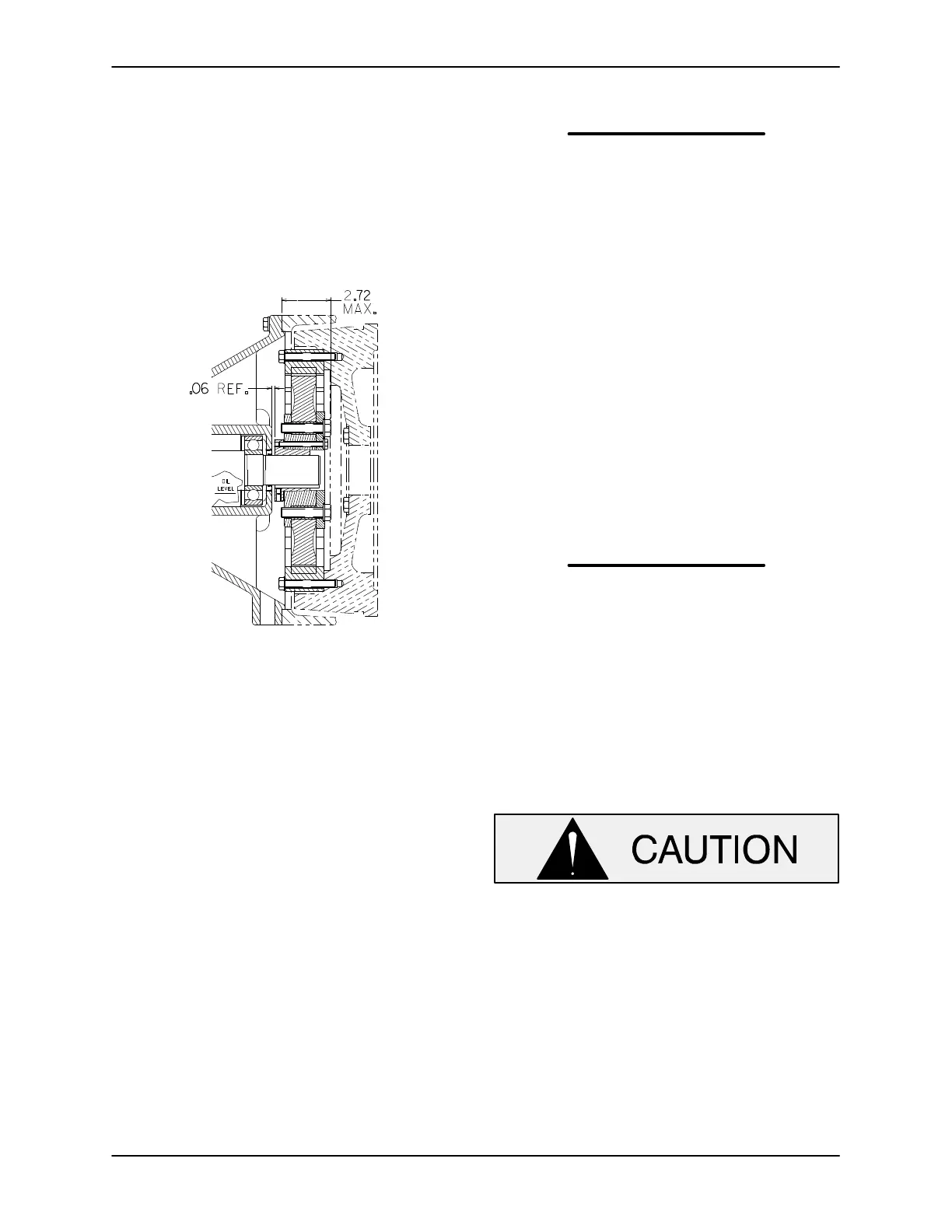
The distance between the intermediate shoulder
and the clamp ring mounting capscrews (34)
should be no greater than 2.72 inches maximum,
as shown in Figure 6. This dimension is critical to
assure adequate clearance between the coupling
and the engine flywheel after reassembly. If re-
quired, adjust this dimension by loosening the set-
screw in the tapered bushing and sliding the flex-
ible portion of the coupling on the shaft.
Figure 6. Coupling Mounting Dimensions
To prevent excessive wear or binding on the cou-
pling, the flexible portion of the coupling must be
squarely positioned on the tapered bushing. To
check, place a straight-edge across the face of the
clamp ring mounting screws (34) and measure
from the machined face of the intermediate to the
straight-edge in 3 or 4 places around the intermedi-
ate shoulder. The dimension should be the same at
each point, and should be no greater than 2.72
inches maximum, as shown in Figure 6. If the di-
mensions are not the same all the way around the
coupling, loosen the hardware (32 and 33), re-set
the coupling on the tapered bushing (37) and re-
tighten the fastening hardware. If the coupling-to-
intermediate dimension is greater than 2.72 inch-
es, check the positon of the tapered bushing on
the shaft and set to 1/16 inch as shown in Figure 6.
NOTE
The hardware kit (18, Figure 1) supplied with a new
pump endcontains both metric and SAE hardware.
When installing a new pump end, make sure to use
the correct hardware for the engine, and discard
the unused hardware.
If the complete coupling assembly is being re-
placed, apply ‘Loctite Retaining Compound No.
242’ or equivalent to the threads of the hardware
(21 and 22) and secure the connection ring (27) to
the engine flywheel by torquing the hardware to 45
ft. lbs. (540 in. lbs. or 6,2 m. kg.).
Using a suitable lifting device, position the as-
sembled coupling and pump so the flexible portion
of the coupling seats inside the outer ring attached
to the engine flywheel.
NOTE
To ease installation, lightly lubricate the rubber por-
tion of the coupling with a non-petroleum based
lubricant such as vegetable oil or glycerin, or a sili-
con-based lubricant such as WD40" or equivalent.
Do not use petroleum-based lubricants, or any oth-
er substance which may soften or otherwise dam-
age the rubber.
Secure the intermediate to the engine bellhousing
with the hardware (19 and 20).
Pump Casing and Wear Ring Installation
If the wear ring (50) was removed, position the re-
placement ring in the pump casing with the lip on
the I.D. of the wear ring toward the bore shoulder.
Press the wear ring into the pump casing until fully
seated.
The wear ring must seat squarely in the
casing bore or binding and/or excessive
wear will result.
Install the pump casing gasket (5) over the studs
(8) and secure the casing to the seal plate with
hardware (9 and 10). Torque the nuts to 41 ft. lbs.
(492 in. lbs.).
NOTE
Wear ring binding, improper casing gasket installa-
tion, or shaft distortion due to improper shimming
can cause seal leakage. Use caution to assure


 To Next Page