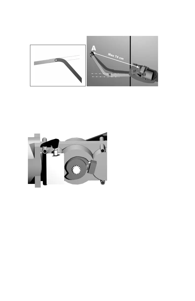
on fig. 5-6. Fix the bracket A verifying that the distance between
the centre of the motor shaft and the centre of the bracket A is
NOT more than 74 cm.
Fig.5-6
7- Do a complete movement of the wing verifying the correct
movement of the articulated arm.
8- Verify the fixings and proceed with the electrical connections
9- Adjust the end run cams(A-B) in according to how indicated on
the manual of your control box. (Fig.7)
Fig.7
10- Place the cap.
11- Install the mechanical stops
MAAINTENANCE :
Periodical.
Check the closing of articulated arm bolts, taking care to cut of the electrical
alimentation, remove the protection carter and look the motor conditions,
eventually clean it.
Extraordinary.
To all eventual operations on the motor, out of the ordinary, please call a
specialized technician.
CONFORMITY DECLARATION:
A-B