Do you have a question about the Grace m101 and is the answer not in the manual?
Basic environmental, electrical, and physical safety guidelines for the equipment.
Explains the 'CAUTION: READ ACCOMPANYING DOCUMENTS' and 'WARNING: ELECTRICAL SHOCK HAZARD' symbols.
Instructions for contacting Grace Design for repairs, upgrades, or return authorization.
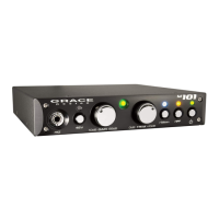
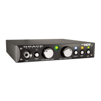
Input for high-impedance instruments or line-level signals.
Powers condenser microphones; LED indicator illuminates red when active.
12-position control for mic input gain (10-65dB) and instrument input gain (-10-45dB).
LED monitors output signal, indicating presence (green) and peak (red) levels.
Provides zero to +10dB of continuously variable output trim.
Activates ribbon mic mode, optimizing signal for ribbon mics; LED is white.
75Hz, 12dB/Octave filter for reducing low-end rumble or proximity effect.
Activates preamplifier circuitry; green POWER LED illuminates when depressed.
Universal AC input (100-240V) for power supply; requires grounded outlet.
Unbalanced TS output connector, wired tip signal, sleeve ground.
Balanced TRS output connector, wired tip positive, ring negative, sleeve ground.
Balanced XLR line output connector, wired pin 2 positive, 3 negative, 1 ground.
XLR input for microphones, supports 48V phantom power on pins 2 and 3.
1/4" TRS jack on front panel for instrument/line input, balanced with tip/ring/sleeve.
Steps for connecting microphone, setting phantom power, and adjusting gain for recording.
Fine output level adjustment and gain boost up to +10dB.
Optimizes for ribbon/dynamic mics, locks out +48V, increases input impedance to 20k Ohms.
75Hz high pass filter reduces low-end rumble or proximity effect.
Diagram illustrating how to use a TRS balanced output as unbalanced.
Diagram for connecting an XLR balanced output to an unbalanced 1/4" input.
Specifies gain ranges for mic and Hi-Z inputs, and output trim control.
Total Harmonic Distortion plus Noise specifications at various gain levels.
Specifications for intermodulation distortion using SMPTE/DIN standard.
Noise levels referred to input for different source impedances (500, 1500, 6000 Ohm).
Common Mode Rejection Ratio values at 100Hz, 1kHz, and 10kHz.
Phase deviation measurements with the High Pass Filter disengaged.
Frequency response curves for mic and Hi-Z inputs.
Input and output impedance values for various connections.
Thresholds for green and red LED indicators on the peak meter.
Maximum output level before distortion occurs.
Physical specifications of the unit, including weight and dimensions.
Power usage of the device.
Details the five-year warranty period, coverage, and exclusions.
Instructions for obtaining warranty service and registering the product.
Records changes made to the manual with dates and initials.
| Type | Microphone Preamplifier |
|---|---|
| Channels | 1 |
| Input Impedance | 8.1k ohms |
| HPF | 80Hz, 12dB/octave |
| Phantom Power | 48V |
| Power Output | Not applicable |
| Damping Factor | Not applicable |