Reassembly
309577K 17
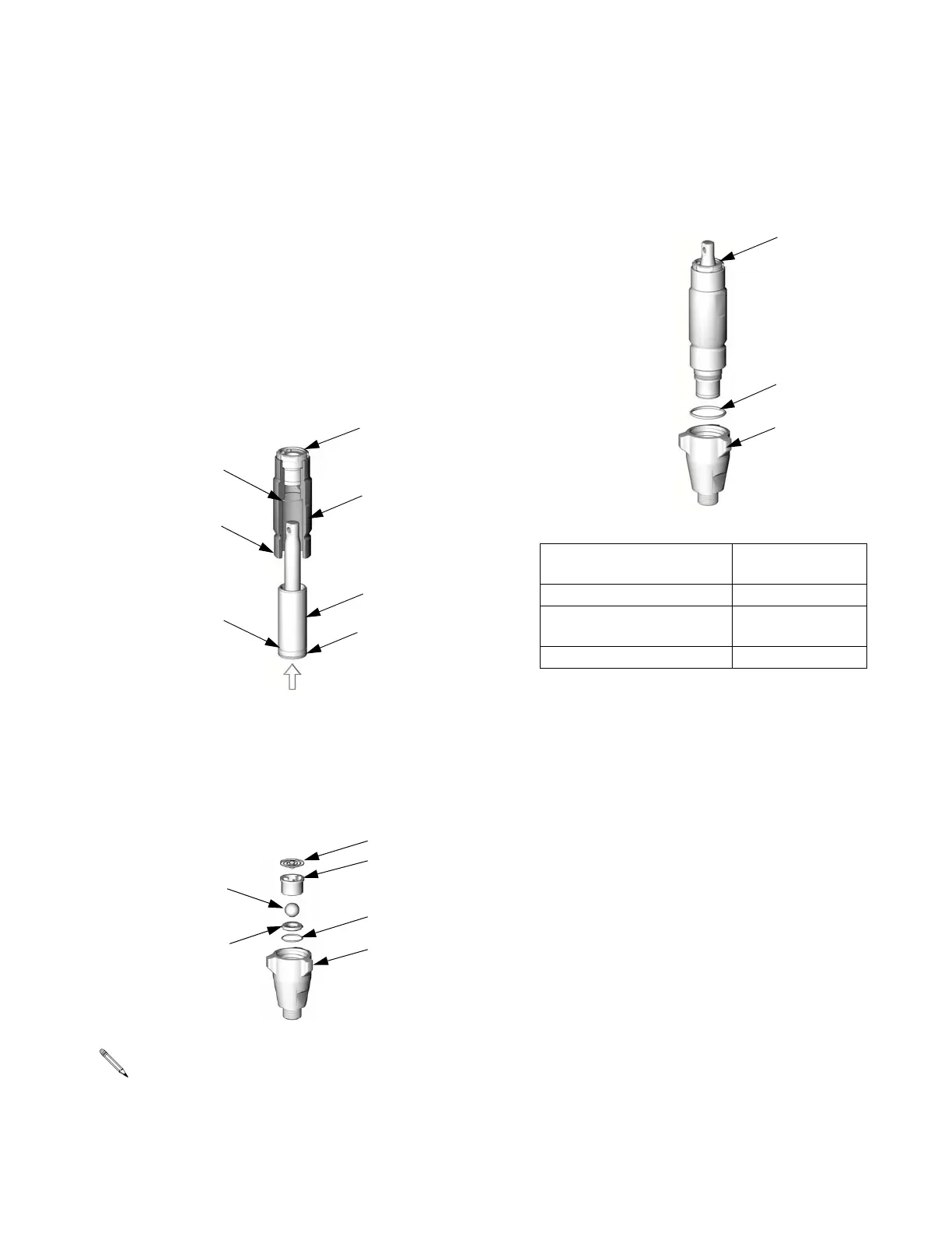
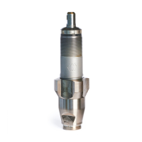
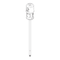
7. Lubricate top 1-2 in. (25-50 mm) of displace-
ment rod (1) and outside of sleeve (4). Grease
o-rings (3*) and place one in cylinder and other
on bottom of sleeve.
8. Slide sleeve/rod assembly into bottom of cylin-
der (2). Drive in with hammer until top of groove
(H) aligns with bottom of cylinder (L). Use plastic
rod to drive displacement rod until 1/4-3/8 in.
(6-10 mm) of its greatest diameter is visible
above packing nut (19).
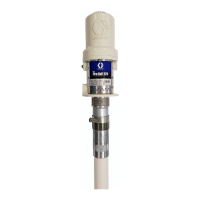
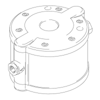
9. Reassemble intake valve with o-ring (10*), seat
(9), and ball (11*). Install ball guide (12). Models
246832 and 245972 only: Install spring (8*) with
screw at top.
Seat may be flipped over and used on other
side. Clean seat thoroughly. No scratches per-
mitted on sealing edge.
TI2674A
19
*3
2
L
4
3*
H
TI2665A
5
*11
9
10*
8*
12
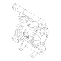
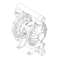
10. Replace o-ring (15*). Install intake valve. Torque
housing (5) as follows, or be sure intake valve is
snug against cylinder.
Model Torque
ft-lb (N•m)
246830 and 245970 65-75 (88-101)
246831, 262647, 245971,
and 262648
75-85 (101-114)
246832 and 245972 145-155 (195-209)
TI2687A
15*
19
5