EasyManua.ls Logo

Graco FIRE-BALL Series User Manual

Graco FIRE-BALL Series
20 pages
To Next Page IconTo Next Page
Page #1 background imageLoading...
Page #1 background image
Instructions – Parts List
GRACO INC.ąP.O. BOX 1441ąMINNEAPOLIS, MNą55440-1441
Copyright 1996, Graco Inc. is registered to I.S. EN ISO 9001
50:1 Fire-Ball
,
50:1 President
, and 75:1 President
400-lb. drum size
Topper Units
306556R
For use with lubricating products only.
Model 226013, 50:1 Ratio Fire-Ball
Pump
5000 psi (34.5 MPa, 350 bar) Maximum Fluid Working Pressure
100 psi (0.7 MPa, 7 bar) Maximum Air Pressure
Model 226018, 50:1 Ratio President
Pump
4000 psi (28 MPa, 280 bar) Maximum Fluid Working Pressure
80 psi (0.6 MPa, 5.6 bar) Maximum Air Pressure
Model 244637, 75:1 Ratio President
Pump
4000 psi (28 MPa, 280 bar) Maximum Fluid Working Pressure
80 psi (0.6 MPa, 5.6 bar) Maximum Air Pressure
Model 204490, Elevator and Inductor
without pump or hose kit
0719
Important Safety instructions
Read all warnings and instructions in this manual.
Save these instructions.

Other manuals for Graco FIRE-BALL Series

Question and Answer IconNeed help?

Do you have a question about the Graco FIRE-BALL Series and is the answer not in the manual?

Graco FIRE-BALL Series Specifications

General IconGeneral
SeriesFIRE-BALL
Maximum Pressure1000 psi
Inlet Size1/2" NPT
Outlet Size1/2" NPT
MaterialAluminum, Stainless Steel
Wetted PartsStainless Steel, PTFE

Summary

Symbols and Safety Warnings

Warning Symbol

Alerts to potential serious injury or death if instructions are not followed.

Caution Symbol

Alerts to potential equipment damage or destruction if instructions are not followed.

Equipment Misuse Hazard

Details risks of improper equipment use and safety precautions to prevent injury.

Skin Injection Hazard

Explains severe injury risk from high-pressure fluid injection and necessary precautions.

Moving Parts Hazard

Details risks of pinching or amputation from moving machine parts and safety measures.

Fire and Explosion Hazard

Describes risks of fire/explosion from grounding, ventilation, sparks, and safety steps.

Toxic Fluid Hazard

Outlines risks from hazardous fluids/fumes and necessary protective measures.

Installation Guide

Grounding Procedures

Instructions and warnings for proper electrical grounding of the pump system.

Pressure Relief Procedure

Steps to safely relieve system pressure before checking or servicing equipment.

Positioning the Elevator

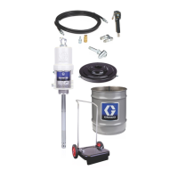
Guidelines for placing the elevator unit for optimal operation and drum access.

Mounting the Elevator

Steps for securely attaching the elevator base to the mounting surface.

Mounting the Pump

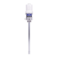
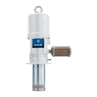
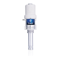
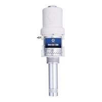
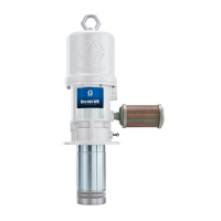
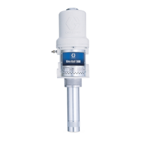
Detailed steps for attaching the pump unit to its support bracket and inductor plate.

Installing the Hoses and Valves

Instructions for connecting air and fluid hoses and installing relevant valves.

Operation Manual

Installing a Drum

Procedure for correctly placing and connecting a drum to the pump system for operation.

Removing a Drum

Steps for safely detaching a drum from the pump system.

Troubleshooting Guide

Service and Maintenance

Removing the Pump

Detailed instructions for safely detaching the pump from the unit for maintenance.

Reinstalling the Pump

Steps for reattaching the pump to the unit after service operations.

Parts Identification

Inductor Plate Assembly (Ref. No. 1)

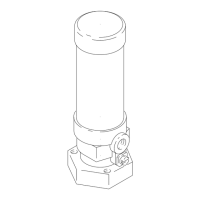
Details parts for the Inductor Plate Assembly.

Inductor Plate Assembly (Ref. No. 17)

Lists components for Monarch/President Inductor Plate Assembly.

Inductor Plate Assembly (Ref. No. 21)

Specifies parts for the 50:1 President Inductor Plate Assembly.

Restrictor Valve Assembly (Ref. No. 42)

Lists components for the Restrictor Valve Assembly.

Snap-Over Valve Assembly (Ref. No. 27)

Details parts for the Snap-Over Valve Assembly.

Air Assist Valve Assembly (Ref. No. 47)

Lists components for the Air Assist Valve Assembly.

Wishbone Support Assembly (Ref. No. 25)

Lists parts for the Wishbone Support Assembly.

Fire-Ball Delivery Hose Kit (Ref. No. 91)

Specifies parts for the Fire-Ball Delivery Hose Kit.

President Delivery Hose Kit (Ref. No. 97)

Lists components for the President Delivery Hose Kit.

Product Dimensions and Weights

Sound Data

Graco Standard Warranty and Support

Graco Phone Numbers

Contact information for ordering and customer support.

Related product manuals