11309941
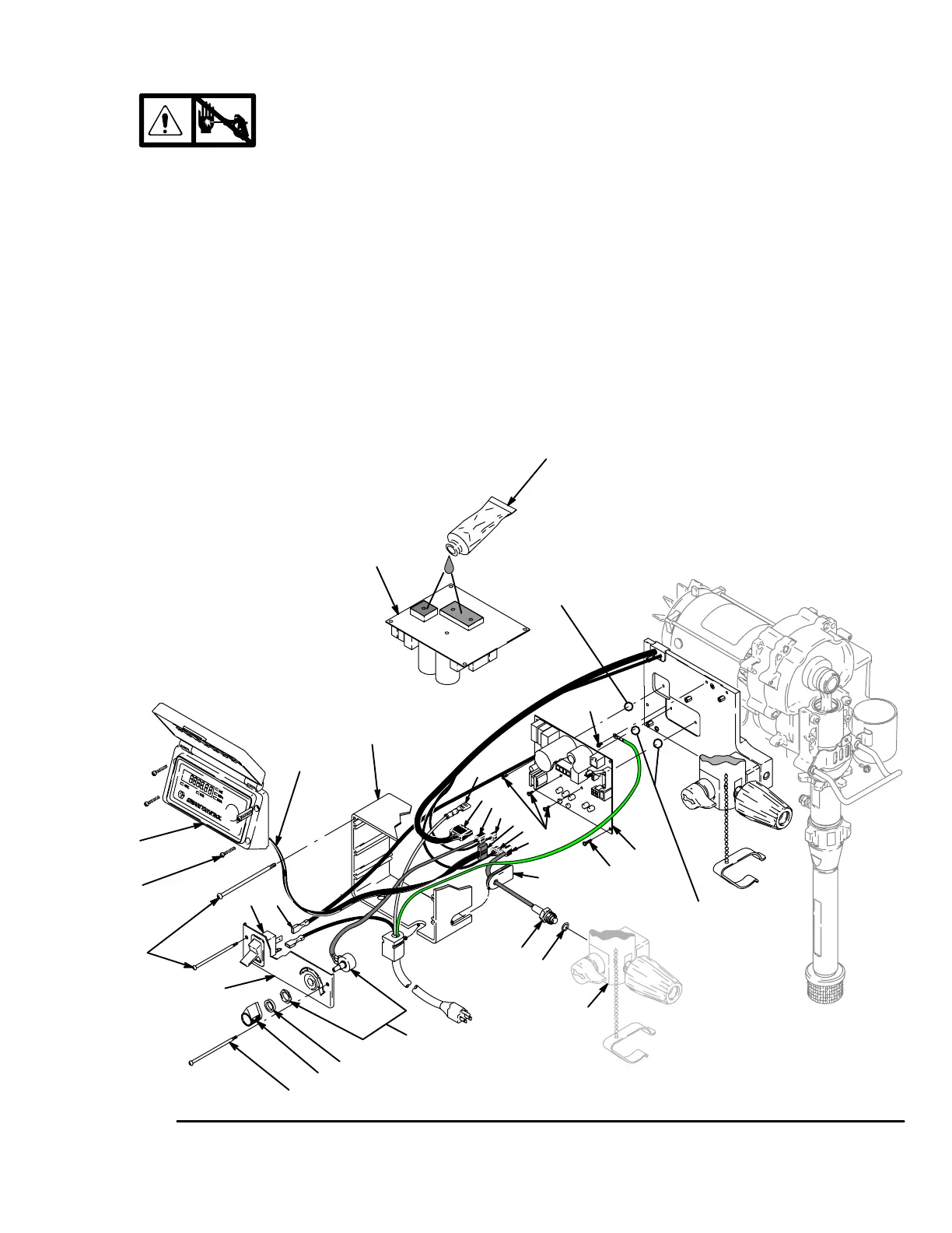
Pressure Control Transducer
Removal
1.
Relieve pressure; page 5.
2. Fig. 3. Remove four screws (38) and cover (96).
3. Disconnect transducer connector (E) from motor
control board (95).
4. Disconnect potentiometer connector (C) from
motor control board.
5. Remove four screws (39) and control box (61).
Allow control panel to hang down freely.
6. Remove transducer (86) and o-ring (20) from filter
base (67).
7. Remove grommet (40) from transducer and save
for reuse.
Installation
1. Install o-ring (20) and transducer (86) in filter base
(67). Torque to 35–45 ft-lb (47–61 N·m).
2. Install grommet (40) onto transducer (86).
3. Connect transducer connector (E) to motor control
board.
4. Install control box (61) and control panel (68) with
four screws (39).
5. Connect potentiometer connector (C) to motor
control board.
6. Install cover (96) with four screws (38).
Fig. 3
39
38
96
68
ti4289a
33
F
G
H
102
95
61
A
26
27
5
95
80
20
40
67
E
A
C
82
115
34
39
Tighten 2 screws
to 7–10 in–lb
Tighten 1 screw
to 18–22 in–lb
120 Vac
D
D
 Loading...