4. Control unit
12 / 40
4.5.2 Operating status display
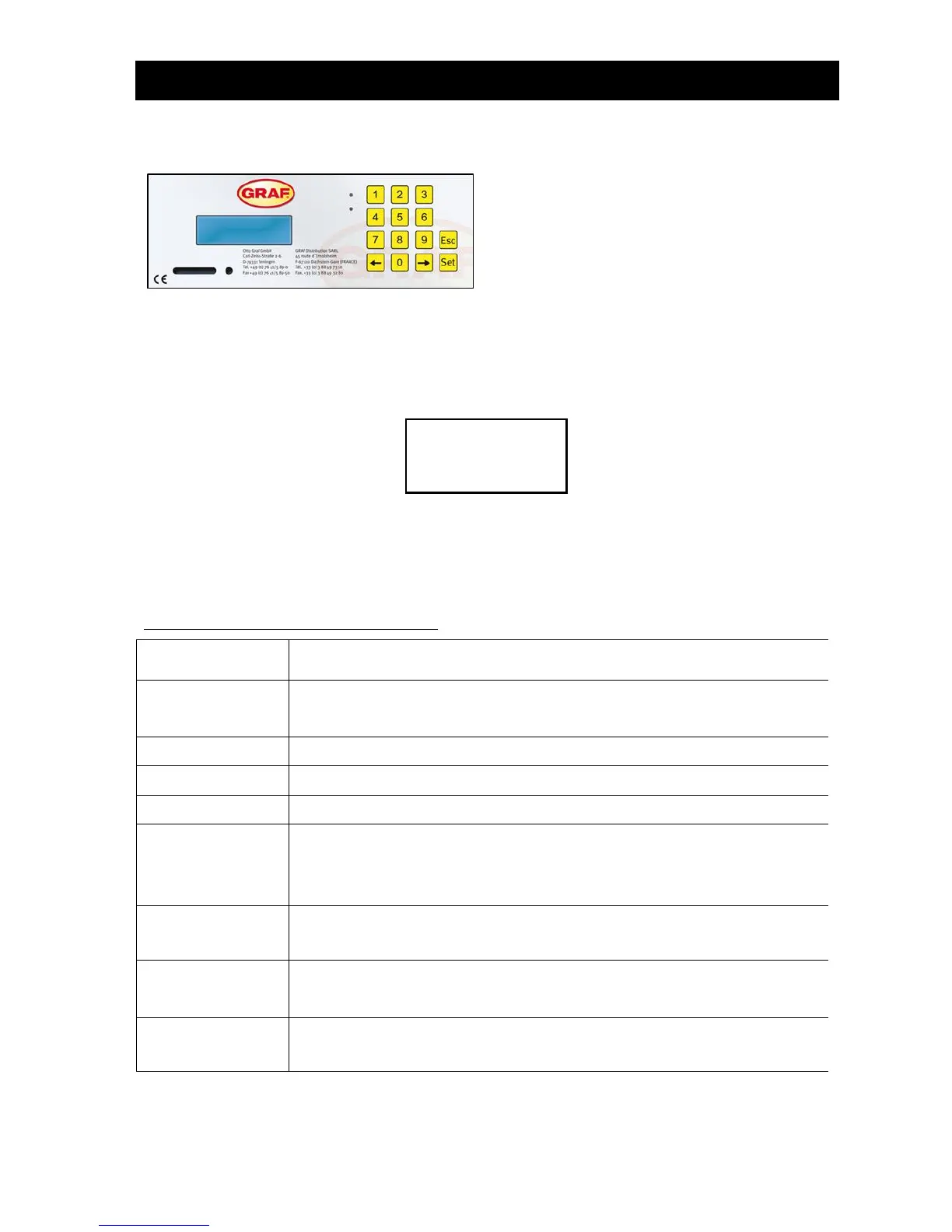
Figure 6 View of KL24plus operating unit
The system's operating status is indicated by the LEDs (Green = Operation / Red = Fault) and by text on
the screen.
In normal operating mode (aeration mode), the display looks like this:
In automatic mode, the liquid crystal display shows the current operating phase and time remaining in this
stage of operation.
If a fault occurs, the red LED switches on. A message appears in the liquid crystal display indicating
which component is faulty (e.g. compressor 0.0A fault).
The following operating phases are displayed:
Aeration is activated intermittently, the aerated sludge is briefly mixed. There are
long pauses in between (reaction times).
Aeration is activated, the system is aerated at intervals.
Rest phase; the aerated sludge settles.
Discharge lifter is activated, the clear water is pumped into the discharge.
Sludge lifter is activated, the excess sludge is pumped out of the last tank back
into the first one.
ONLY with multi-tank systems
Aeration is activated, the system is aerated at intervals (considerably less than in
the "aeration" phase).
Aeration is activated, the system is aerated at intervals, no cleaning cycles are
undertaken.
Display showing time remaining.