4. Control unit
8 / 40
4. Control unit
Connections to the KL24plus control unit 4.1
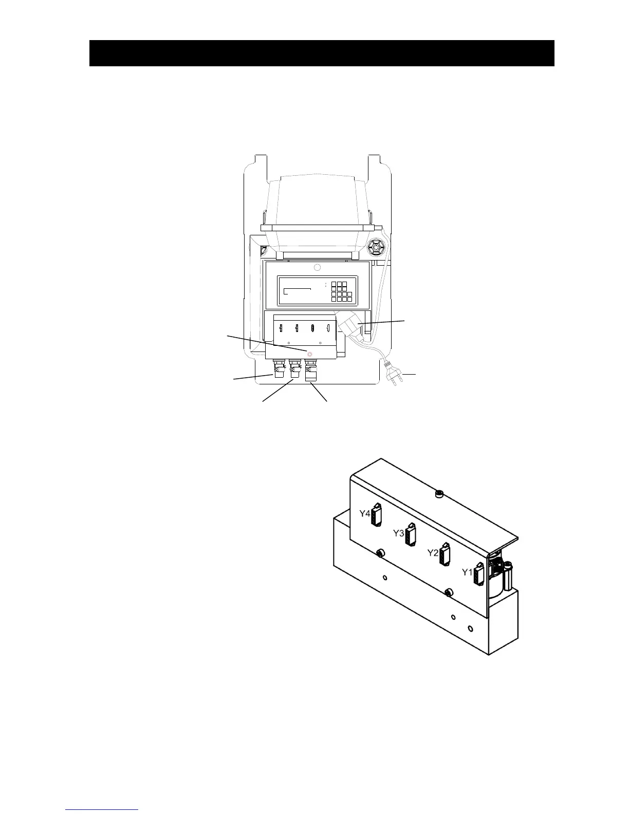
The figures below show the basic structure of the switch cabinet of a two-tank system.
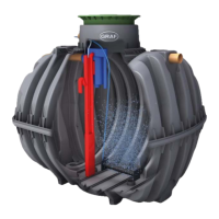
Figure 3: EPP cabinet with 3-way air distributor
The following connections can be found on the switch cabinet:
1. 230V AV ~ 50 Hz mains connection, for con-
necting the control unit to a socket
2. Compressor connection, for connecting the
compressor to the control unit via an integrat-
ed two pin plug
3. Compressor's air connection. This is used to
connect the strip of valves integrated in the
switch box to the compressor
4. Hose connection (19 mm) for connecting the
aeration unit
5. Hose connection (13 mm) for connecting the
discharge lifter
6. Hose connection (13 mm) for connecting the
sludge lifter
7. One unused hose connection