Repair manual GRAMMER seat suspension MSG95EAC – November 2012
Material no. 1 277 338
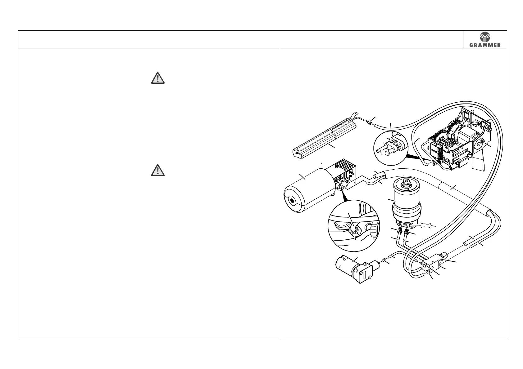
2.1 Overview of components
Page 1 of 7
Pneumatic modules and
connecting diagram
(1) Active module
(2) Control / air reservoir
(3) Quick-release fastener
(4) Air hose (black):
Hose from air distributor (15) to
control (2)
(5) Air hose (blue):
Hose from air distributor (15) to
sensor module (6)
(6) Sensor module
(7) Energy bundle
(8) Air hose (thin)
Hose from air distributor (15) to 2/2
directional valve in the active
module (1)
(9) Air hose (thick):
Hose from air distributor (15) to 3/2
directional valve in the active
module (1)
(10) Air spring
(11) Catch spring
(12) Quick coupling
(13) Air intake hose / air exhaust hose
(14) Air intake hose / air exhaust hose
(15) Air distributor
16 Quick-release fastener screw
WARNING Damage!
Observe the instructions stated in
Chapter 3.9 and in Chapters 3.14 to
3.16 when pulling off the air hoses
(4, 5, 8) from the quick-release
fastener screw!
(17) Air hose
(18) Nozzle
(19) Compressor
WARNING Damage!
Please observe the notes stated in
Chapter 3.8 when pulling off the air
hose (17) at the connection of the
compressor (19).
(20) Retaining ring of quick coupling
2852
16
15
16
16
2
3
7
1
8
5
20
5
6
19
13
18
9
8
17
12
11
10
9
8
14
12
16
4