3 4
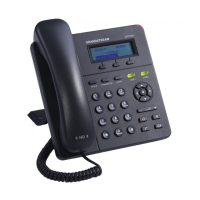
PHONE SETUP:
To setup the GXP1400/1405, follow the steps below:
1. Connect the handset and main phone case with the phone cord.
2. Connect the LAN port of the phone to the RJ-45 socket of a hub/switch or a
router (LAN side of the router) using the Ethernet cable.
3. Connect the 5V DC output plug to the power jack on the phone; plug the power
adapter into an electrical outlet.
4. The LCD will display provisioning or rmware upgrade information. Before con-
tinuing, please wait for the date/time display to show up.
5. Using the phone embedded web server or keypad conguration menu, you can
further congure the phone using either a static IP or DHCP.
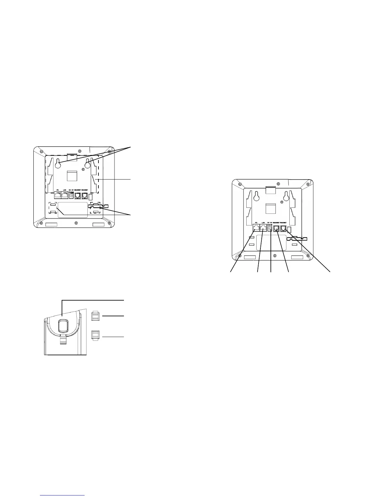
Slot for the phone
stand if placing the
phone on the table
LAN Port Power Handset Port
Wall mount holes
are available
Slot for the wall
mount spacers if
placing the phone
on the wall
Installing the Phone (Phone Stand):
For installing the phone on the table with the phone stand, attach the phone
stand to the bottom of the phone where there is a slot for the phone stand (upper
part, bottom part).
Installing the Phone (Wall Mount):
1. Attach the two wall mount spacers to the slot for wall mount spacers on the
back of the phone.
2. Attach the phone to the wall via the wall mount hole.
3. Pull out the tab on from the handset cradle (See gure below).
4. Rotate the tab and plug it back into the slot with the extension up to hold the
handset while the phone is mounted on the wall (See gure below).
Tab with extension up
Handset Rest
Tab with extension down
PC Port Headset Port
CONNECTING THE PHONE:
 Loading...