26
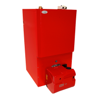
Grant Vortex External Module
Fig. 19 - 50/70 rear view (showing pump assembly)
6 - BOILER INSTALLATION
See Figs. 18 and 19
1 The kit includes the following items:
Pressure relief valve and automatic air vent
Manifold pipe
10 litre expansion vessel with flexible hose and
sealing washer
Expansion vessel mounting bracket
Filling loop kit
Pressure gauge (mounted on compression tee)
6 m head circulating pump with 22 mm gate type
valves
15 mm copper pressure relief valve discharge pipe
(in two pieces with push-fit connector)
Pump support bracket (with fixing screws)
2 Unscrew and remove the two nuts and washers
from the two cleaning door studs. Remove cleaning
door from boiler.
3 Remove the ½" BSP black iron plug from the front
of the boiler waterway, using a
3
/
8
" drive socket
wrench.
4 Fit the ½" BSP straight connector end of the
flexible expansion vessel hose into the tapping on
the front of the waterway using a suitable thread
sealant.
5 Fit the ¾" BSP connection on the flexible
expansion vessel hose to the vessel using the black
rubber sealing washer supplied and tighten the
union nut.
6 Replace the cleaning door on the two door studs.
Fit the expansion vessel mounting bracket onto the
studs. Replace the nuts and washers and re-tighten
to secure door and bracket.
Sealed system kit - 50/70
6.5a
7 Fit the pressure relief valve and automatic air vent
onto the manifold pipe. Then fit the manifold pipe
end into the 22mm compression connector on the
boiler flow pipe. Refer to Fig. 18.
Fig. 18 - 50/70 top view (showing automatic air
vent, pressure relief valve and manifold)
Pressure relief valve
Manifold
pipe
Automatic
air vent
Pressure relief
valve discharge pipe
Tectite
connector
8 Fit both 22 mm pump valves to the circulating
pump using the sealing washers provided.
9 Fit the pump support bracket, with the screws
provided, using the two holes in the left hand side
panel flange (viewed from rear of boiler as shown
in Fig. 19).
Pump support
bracket
Screws
Pump and
valve assy.
 Loading...


