6
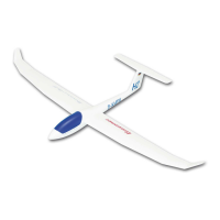
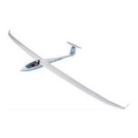
Cut down the servo output lever as shown in the photo below.
Fit the output arm on the servo output shaft, facing outward, i.e. towards the wingtip.
This arrangement means that the servos do not need to be reversed; this may be
useful if you are using a “simple” (non-computer) RC system.
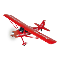
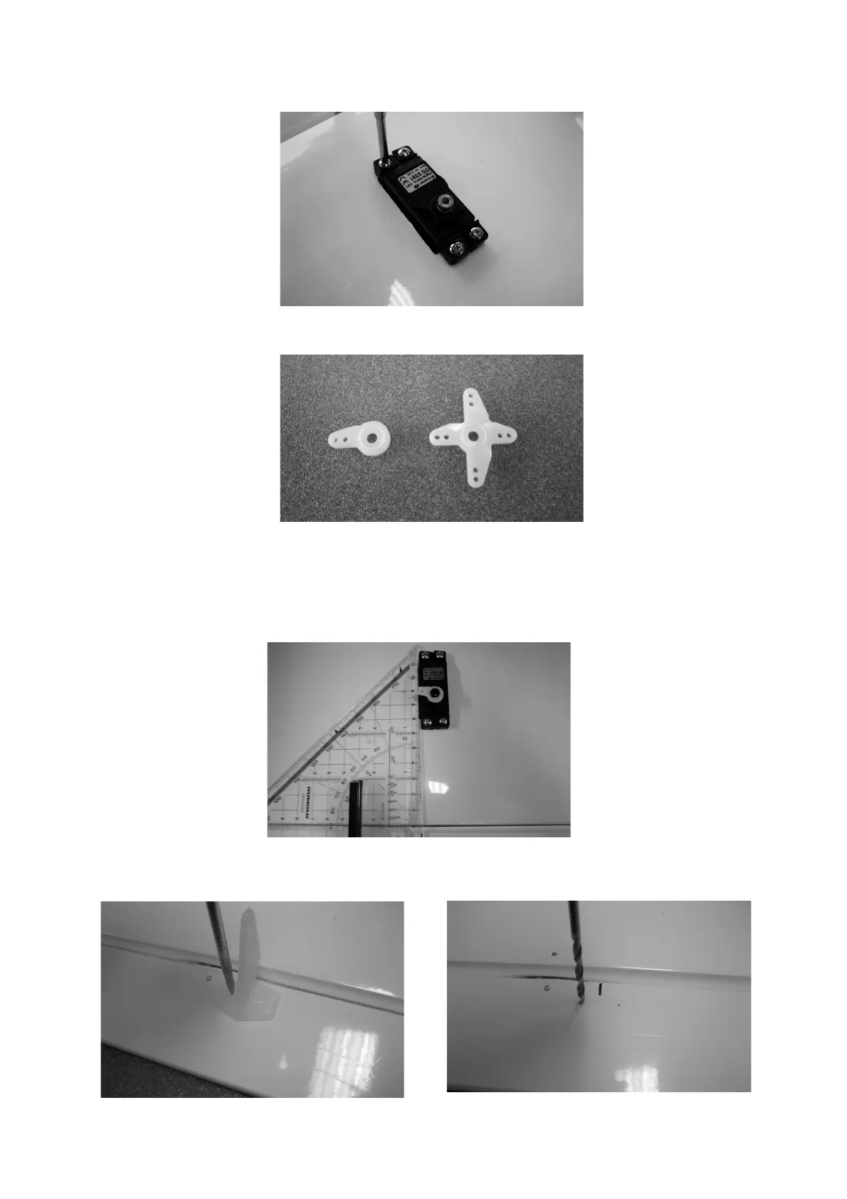
Place a setsquare on the wing as shown in the photo, and mark the position of the
servo output arm linkage hole on the aileron, at right-angles to the control surface.
Mark the position of the horn holes on the aileron, and drill 2 mm Ø holes at the
marked points.
 Loading...