GRAUPNER GmbH & Co. KG D-73230 KIRCHHEIM/TECK GERMANY
We reserve the right to introduce modifications. Not liable for printing errors! 12/2011
Made in
Vietnam
15
The ON/OFF switch for the RC system (PRX 3A) can be installed on the right
fuselage side wall. Use a hot soldering iron to melt through the openings for the slide
switches and the diode. Use the screws that come with the switch to install them in
the side of the fuselage.
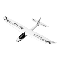
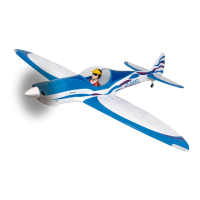
Assembling the TWISTER
To connect the control surface servos to the receiver it is recommended that an
extension cable Order No. 3935.18 be inserted into the corresponding receiver
socket. The receiver battery is placed upon foam material and attached to the
fuselage so that it can not slide. Use the connector tube to attach the wing halves to
the fuselage. Connect the connecting cables of the control surface servos using the
extension cables. Push the wing into the fuselage far enough that the two wing
halves can be pulled up against the fuselage using the latches, which are accessible
from the underside of the two wing halves.
The two wing latches are turned clockwise using a Philips screwdriver until the two
wing halves abut the fuselage.
Place the fuselage cover onto the fuselage opening so that the two pegs fit into the
holes in the bulkhead. The fuselage cover is fastened by snapping the two spring-
loaded locking mechanisms into place.
 Loading...