I
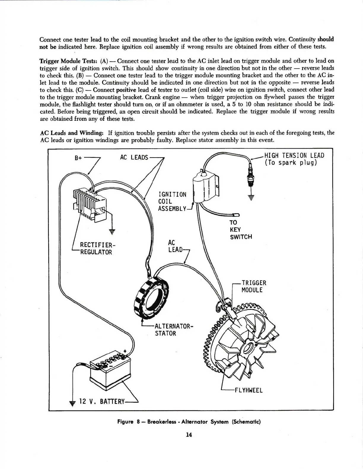
Connect
oae tester
Iead
to the coil mounting
bracket and the other to the ignition
switch wire. Continuity
slrould
not
be
indieated here. Replace
ignition
coil assembly if
wrong results are obtained from
either of these tests.
Trigger
Module Tests:
(A)
*
Connect
one
tester
Iead to the AC inlet lead
on
trigger module
and other
to lead
on
l
trigger side of
ignition switch. This should show continuity
in one &rection but not in the
other
-
reverse leads
l
to check
this.
(B)
-
Connect one tester lead
to the trigger module mounting
bracket and the other to the
AC in-
l
let lead
to the module. Continuity
should
be indicated in
one
direction
but
not
in the opposite
*
reverse
leads
to
check
this.
(C)
-
Connect
positive
Iead
of tester
to outlet
(coil
side)
wire
on
ignition switch, connect other
lead
tothetriggermodu1emountingbracket.Crankengine_whentriggerprojectiononfywheelpassesthetrigger
module,
the llashlight tester should
turn on, or
if an ohmmeter
is used, a
5 to
10 ohm resistance should
be indi-
l
cated.
Before
bein[
triggered, an open
circuit
should
be
indicated.
Replace
the trigger module if
wrong resu]ts
.
are obtained
from any of these
tests.
l
AC
Leads and Winding:
If
ignition trouble
persists
after the system checks
out in each of the
foregoing
tests,
the
AC leads
or ignition windings
are
probably
faulty. Replace
stator assembly in this
event.
AC LTADS
r-?if'
TENSION LEAD
spark
plug)
IGNITION
cot
r
ASSEMBLY
TO
KEY
swlrcH
RECTIFIER-
REGULATOR
TRIGGER
MOOULT
ALTERNATOR.
STATOR
LYHI.IEEL
12
V.
BATTERY.
Figure
8
-
Breqkarlesr
-
Aliernstor $yrtem
(Schemotid
14