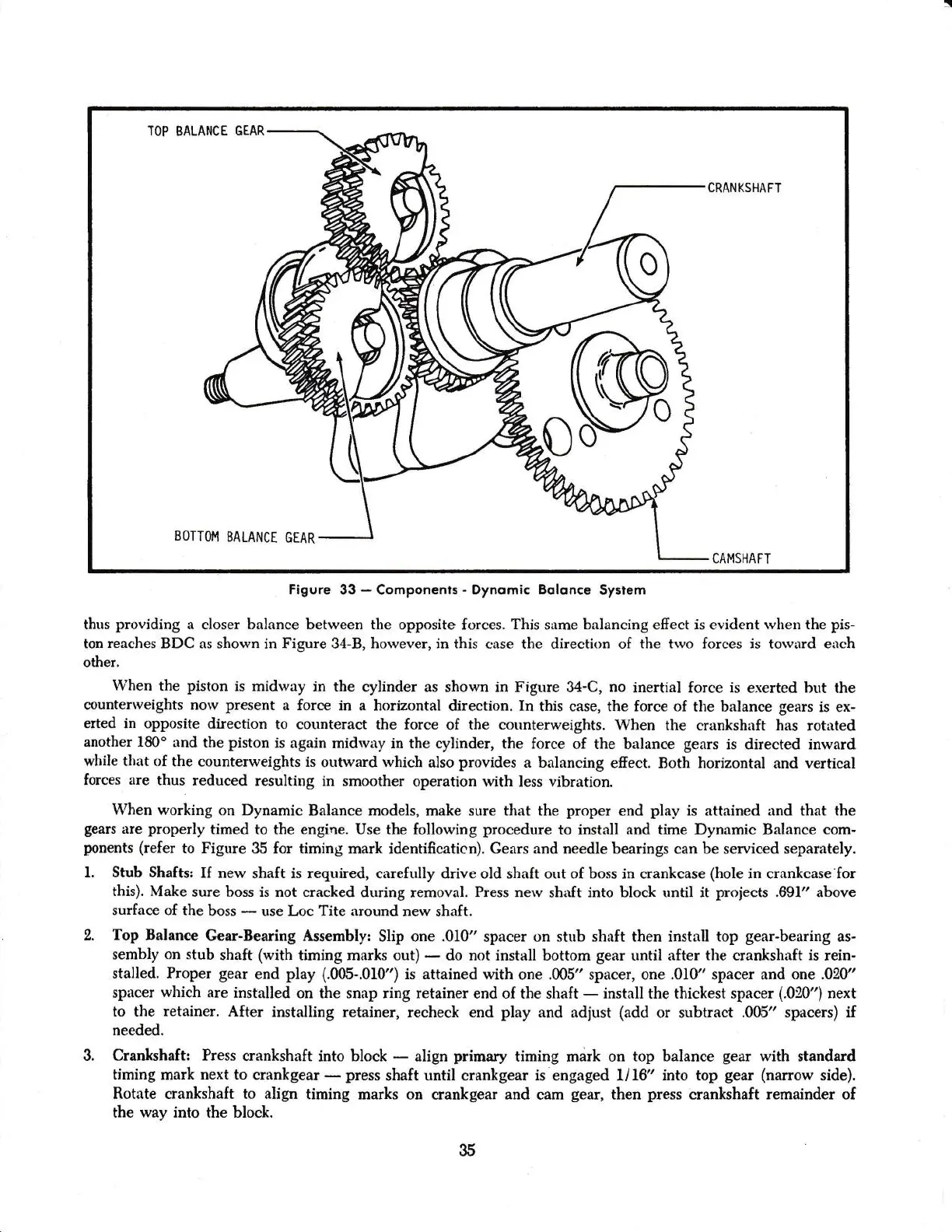
BOTTOI'1
BALANCT
GEAR
CRANKSHAFT
CAMSHAFT
Figure 33
-
Componenls
-
Dynomic
Bqlonce
Syslem
thus
providing
a
closer
balance between
the opposiie forces.
This
s:rme
balancing
efrect is evident
rvhen the
pis-
ton reaches BDC as
shown in Figure 34-B,
horvever,
ir this *rse the direetion of
the trvo
forces is torvard
errch
other.
When the
piston
is
midway in
the cylinder as shown
in Figtue 34-C,
no
inertial force is
exerted but the
ctunterrveights norv
present
a force in a
horizontal
dheetion.
In
this case, the
force
of
the balance
gears
is ex-
erted in opposite
direction
to counteract
the
force
of
the counterweights.
When the crankshaft has
rotrrted
another l80o and
the piston
is
again midrvrry in the
cylinder, the {orce
of
the
balance
gears
is directed inward
while
that of
the
counterweights is
outward rvhich
also
provides
a balancing
efiect.
Both
horizontal
and vertical
forces
are
thus
reduced
resulting in smoother
operation with less
vibratioa.
When working
on Dynamic Balance
models, malce
sure that the
proper
end
play
is
attained
rrnd
that
the
gears
are
properly
timed to the
engine.
Use the following
procedure
to
install and
time
Dynamic Balance
com-
ponents
(refer
to Figure 35 for timing
mark identiffcaticn). Gears and needle bearings can be
serviced
separately.
1. Stub Shafts:
I[
new
shaft is required, c:rrefully drive old shaft out of
boss in crarkcase
(hole
in crankcase'for
this).
Make
sure boss is
nct cracked during
removal.
?iess nerv
shnft
into block until
it
proieets
.891" above
surface
of the
boss
*
use
Loc Tite
around
new
shaft.
2.
Top Balance
Gear-Bearing
fusembly: Slip one .010"
spercer on
stub shaft
then install
top
gear-bearing
as-
sembly on stub
shaft
(with
timing marks out)
-
do not install bottom
gear
until after the crankshaft
is
rein-
stalled. Proper
gear
end
play
{.004.010")
is
attained with one .005" spacer, one .010" spacer and
one .020"
spircer
which
are installed
on the snap
ring retainer end of the
shaft
-
irutall
the
thickest spacer
(.020")
next
to the
retainer.
After
installing
retainel recheck end
play
and adjust
(add
or subtract
.00.5"
spacers) if
needed.
3. Cranlcshaft:
Press
crankshaft
into
block
*
align
primary
timing md,rk
on
top
balance
gear
with standard
timing
mark
next
to crankgear
-
press
shaft until crankgear
is
engaged
U16"
into top
gear
(narrow
side).
Rotate crankshaft to align
timing marks
on crankgear and cam
gear,
then
press
erankshaft
remainder of
the way into the
block.
35