Ctankshaft Installation
a.
Place
block
on
base
of arbor press
and
carefully insert
tapered
end
of crankshaft
through
inner
race of
antifriction bearing.
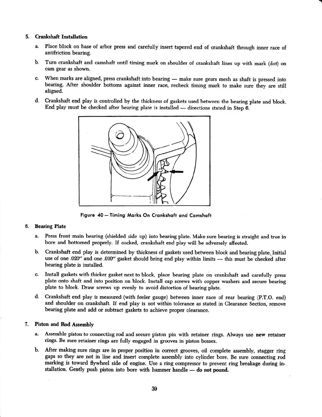
b.
Turn
crankshaft
and
camshaft until
timing mark on
shoulder
of
crankshaft
lines up with
mark
(dot)
on
cam
gear
as shown.
c.
When marks
are
aligned,
press
crankshaft
into
bearing
-
make sure
gears
mesh
as shaft is
pressed
into
bearing.
After
shculder
bottoms
against inner race, recheck
timing
mark
to make
sure they are still
aligned.
d.
Crankshaft
end
play
is controlled
by
the
thickness of
gaskets
used between
the beariag
plate
and
block.
End
play
mlst be
checked after
bearing
plate
is
installed
*
directions
stated in Step 6.
Figrrc
40
-
Timing
llorks
On
Crsnkshofr ond Comshoft
3earing
Plate
a.
Press front
maia bearing
(shielded
side up) into bearing plate.
Make su:e bearing
is shaight
and tnre
in
bore
and bottomed properly.
If
coclced,
erankshaft end
play
will be adversely afiected.
b. Crankshaft
ead
play
is
determined by thickness
of
gaskets
used
between block
and bearing
plate..Initial
use of
one .0ff'
and one .010'
gasket
should
bring
end
play
within limits
*
this must be
cheeled after
bearing
plate
is installed.
c. Install
gaskets
with
thicker
gasket
next
to block,
place
bearing
plate
on crankshaft and
carefully
press
plate
onto shaft
and into
position
on
block. Install
cap screws with
copper washers
aad
secure
bearing
plate
to
block.
Draw screws
up
evenly to avoid distortion
of
bearing
plate.
d.
Crankshaft
end
play
is
measured
(with
feeler
gauge)
between
inner race of rear bearing
{P.T.O.
end)
and
shoulder
on
crankshaft.
If end
play
is
not
within
tolerance
as stated in Clearance
Section, remove
bearing
plate
and
add
or subtract
gaskets
to achieve
proper
clearance.
1.
Piston and
Rod Assembly
a. Assemble piston
to connecting rod
and secure
piston pin
with retainer
rings. Always use nely
retainer
rings. Be
sure:etainer
rings
are fully
engaged in
grooves
in
piston
bosses.
b. After making
sure
rings are in
proper
position
in correet
grooves,
oil
complete assemblR stagger
ring
gaps
so they
are not
in line and
insert complete
assembly into
rylinder
bore.
Be sule connecting rod
markiag
is
toward
flywheel
side
of engine. Use
a
ring
compressor to
prevent
ring
brealage
duriag
in-
stallation. Gurth
push
piston
into bore
with hammer handle
-
do not
1nund.
39