Differential
Before assuming internal
swiftamatic
diftculties, carefr.rlly examile
the
external
linkage
and
parts
for b:nding.
Caretully
check
the
Jollowing;
1.
Check
linkage
for
binding,
sheared roll
pin,
broken
cotter
pins"
2. Check to see that the control arm
and
level assembly is not
binding on the
cross shaft
weldment.
3. Chect to see that the two-speed
extension
spring
is in
place.
4. Check bolts and nuts securing
the
frame to
chassis
for tightness.
Torque to 65 ft.
lbs.
5.
Check
stationary clutch bolt.
3e sure it is not sheared.
8. Raise the rear tires. ?urr:
one
wheel
by hand. The otl'rer
wheel
should
turn
the
opposite
direction. Check for
tight spots
or roughness
while
turning.
lf these cheeks
do
not isolate
the
difficulty,
it
will
be necessary to examine
the internal
parts
of the two
speed
shifting
mechanism
and
differential.
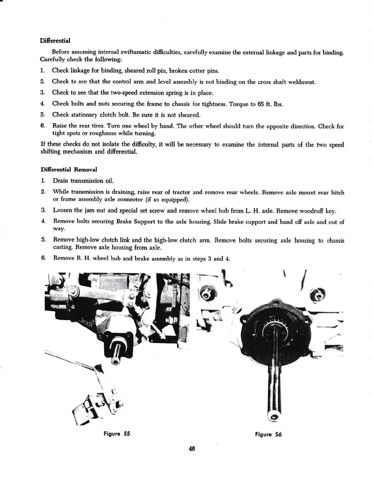
DiEerential Removal
1. Drain
transmission oil.
2.
11&ile
transmission is
draining,
raise rear
of tractor and remove rear wheels.
Remove axle
mount rear litch
or
frame asscmbly
axle
con:rector
(if
so equipped).
3. Loosen
tle
y'am
nut aad
special set
screw and rernove
rvheel
htrb
from
L.
H.
axle, Remove
rvoodruff
key.
4. Remove
bolts
securing
Brake
Support to the
axle housing. Slide brake
support and band
oS a.rle and out
o{
way.
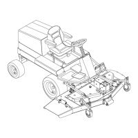
Remove
high-low
clrrtch
link and
the highJorv
clutch
arm.
Remove bolts
securing
axte
holsing to classis
casting. Remove
axle housing
from
axle.
Remove
R. H.
wheel
hub
and
brake assembly
as
in
steps 3 and 4.
a
-r-*
-
!
x,1
?t
(fl,
:
/ffi,
r?T
-
f,l
F\-q I
r&
figurc 55
,t16
Figure
56