T
Tamara DunnAug 3, 2025
What to do if my Gravely Lawn Mower will not crank?
- JJacob MaysAug 3, 2025
If your Gravely Lawn Mower will not crank, the suggested solution is to charge the battery or replace it.
What to do if my Gravely Lawn Mower will not crank?
If your Gravely Lawn Mower will not crank, the suggested solution is to charge the battery or replace it.
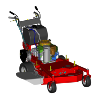
| Brand | Gravely |
|---|---|
| Model | 988075 |
| Category | Lawn Mower |
| Language | English |
Explanation of safety symbols and their meaning to highlight precautions.
Defines signal words like DANGER, WARNING, and CAUTION for hazard levels.
General safety rules including walk-around inspection and area safety.
Safe procedures for refueling the unit with caution regarding fuel hazards.
Describes how to operate the steering levers for directional control.
Procedures for initial adjustment and readjustment of steering levers.
Procedure for adjusting the Power Take-Off (PTO) clutch settings.
Chart to diagnose engine problems with causes and corrective actions.
Step-by-step instructions for removing the engine from the unit.
Explanation of the operator presence control linkage and its function.
Troubleshooting steps if the unit does not move or mow.
Chart for diagnosing fuel system problems with causes and corrective actions.
Safety precautions, setup, and handling of batteries.
Procedures for charging the battery, including specific gravity checks.
Explanation of switch types (N.O./N.C.) and testing methods.
Explanation and testing procedures for solenoids and relays.
Procedure for checking the PTO clutch coil resistance and current draw.
Procedures for checking electrical components on Pro 200 Kohler engine.
Wiring diagrams for various Pro models to illustrate circuit connections.
Overview of electrical system components for specific models.