GB - 34
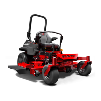
6. Measure the height of the blade tips on
both 1 and 2 and adjust the front
adjustment bolts (see figure 20, item 14)
and the rear U-bolts to ensure the deck
is level from left to right.
7. Rotate the mower blades 90° so they
are parallel to the mower deck. Use the
rear adjustment bolts to adjust the deck
so that the rear blade tip is 1/8” higher
than the front blade tip on the same
blade.
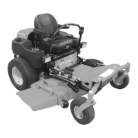
Measure the blade heights to make sure they
match what is shown on the height of cut dial.
The height is measured as the distance
between the ground and the bottom of the
blade. If the blade height does not match the
dial height, see Synchronizing Height Of Cut
below.
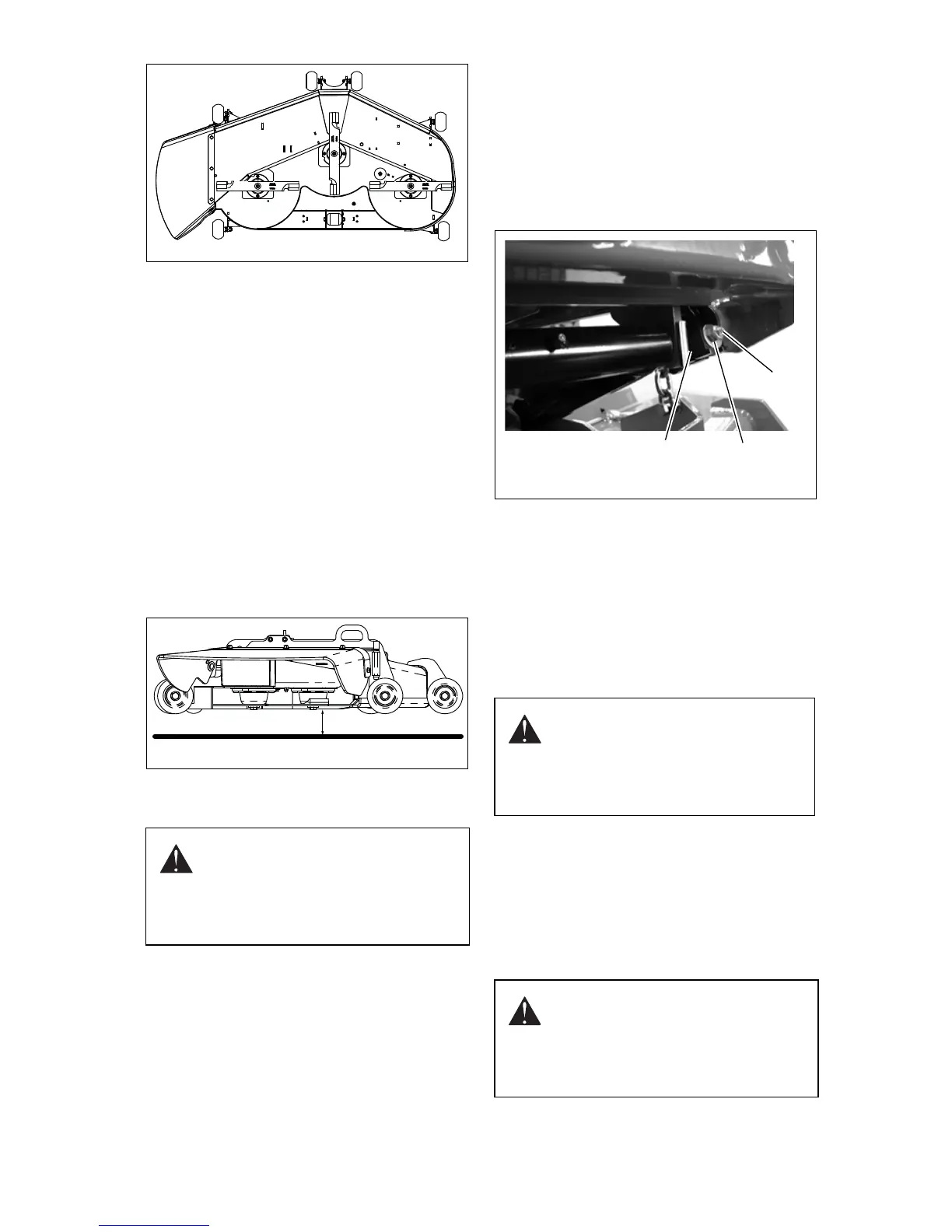
Synchronizing Height Of Cut
(Figure 23)
NOTE: Make sure the deck is level before
synchronizing the height of cut dial with the
deck blade height.
1. Raise the mower deck to the transport
position. Take the weight off of the deck
lift linkage by inserting wood blocks
under each corner of the deck and
slowly lowering it until it is resting on the
blocks.
2. Loosen the 1/2-13" hex nut (1). If the
blade height is lower than the height of
cut knob, loosen the 1/2-13 x 1.75" (2)
bolt which runs through the height of cut
rotation adjustment weldment (3). If the
blade height is higher than the height of
cut knob, tighten the 1/2-13 x 1.75" bolt
which runs through the height of cut
rotation adjustment weldment.
3. Tighten the 1/2-13" hex nut back down
to lock it into position.
4. Raise the deck back to the transport
height and remove the blocks from
below the deck. Measure the blade
height again to ensure it now matches
the height on the dial. If not, repeat until
the two heights are synchronized.
DRIVE ADJUSTMENTS
Steering and motion controls should be
uniform during forward and reverse motions.
The steering control levers should always
return to neutral when released from the
reverse position.
AIR CLEANER SERVICE
(Figure 24)
CAUTION: Stop the engine, put
the steering control levers in the
park position and remove the key
from the ignition before
performing any maintenance or
repairs on this unit.
CAUTION: Stop the engine, put
the steering control levers in the
park position and remove the key
from the ignition before
performing any maintenance or
repairs on this unit.
CAUTION: Touching hot surfaces
can burn skin. The engine and
components will be hot after the
unit has been running. Allow the
engine and components to cool
before servicing the unit.