GB - 26
MOWER DECK
Removal (Figure 16)
NOTE: Only remove PTO belt from electric
clutch.
1. Remove PTO belt from electric clutch
(see PTO Belt on page 28).
NOTE: Perform steps 2 and 3 for mechanical
lift mower decks only (992210, 212).
2. Raise mower deck to transport position
to reduce spring tension(see Mower Lift
Pedal (992210, 212) on page 15).
3. Remove mechanical lift spring from each
side of unit.
4. Lower mower deck all the way down.
5. Remove link chains from mower lift arms
(Figure 17).
6. Remove mower mounting arms from
frame.
7. Slide mower deck out from under unit.
Installation (Figure 17)
1. Slide mower deck under unit.
2. Install mower mounting arms on frame.
3. Install link chains on the mower lift arms.
NOTE: Perform steps 4 and 5 for mechanical
lift mower decks only (992210, 212).
4. Raise mower deck to transport position
(see Mower Lift Pedal (992210, 212) on
page 15).
5. Install mechanical lift spring on each
side of unit (Figure 16).
6. Install PTO belt on electric clutch (see
PTO Belt on page 28).
7. Level mower deck (see Leveling the
Mower Deck on page 26).
LEVELING THE MOWER DECK
These adjustments should be made on a
level surface with the tires inflated to the
correct air pressure.
Check Blade Level and Pitch
1. Raise mower deck to a 3 in. (7.62 cm)
cutting height.
2. Shut off engine. Engage parking brake.
Remove the ignition key.
NOTE: Place blocks under the bottom edge
of the deck, not under the reinforcement bar
welded along deck face (Figure 18).
3. Place blocks at each corner of the deck
to support the weight of the deck.
4. Turn the blades so the blade ends point
left to right across the width of the deck.
DANGER: MOVING PARTS can
cut or amputate body parts.
ALWAYS wait for moving parts to
stop before performing
maintenance or service.
CAUTION: Use care when
releasing mechanical lift spring
tension. Keep body parts well
away from springs when
performing this operation.
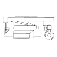
Figure 16
1. Eye-Bolt
2. Mechanical Lift Spring
OF4040
21
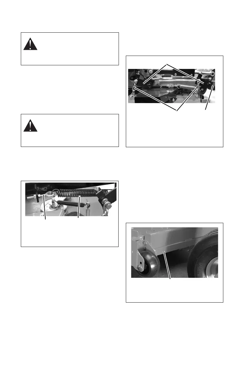
Figure 17
1. Link Chain
2. Mower Mounting Arm
3. Mower lift Arm
2
1
3
Figure 18
DO NOT place blocks
under reinforcement bar.