C
Christopher RodriguezAug 1, 2025
What to do if my Gravely Lawn Mower will not crank?
- MmcculloughlisaAug 1, 2025
If your Gravely Lawn Mower will not crank, charge the battery or replace it.
What to do if my Gravely Lawn Mower will not crank?
If your Gravely Lawn Mower will not crank, charge the battery or replace it.
Overview of the service manual's purpose and usage guidelines.
How to order parts and make inquiries using unit numbers.
Information on warranty activation via registration card.
Warning against using non-Gravely parts and warranty implications.
Gravely's right to change products without notice.
How Gravely communicates technical updates to dealers.
Explains symbols for important safety precautions and warnings.
Defines DANGER, WARNING, and CAUTION signal words for hazard levels.
Explains NOTE and IMPORTANT notations used in the manual.
General safety precautions and awareness of local laws.
Emphasizes training for new operators and manual provision.
Guidelines for preparing the work area and gathering tools before service.
Proper procedures for cleaning and storing the unit.
Walk-around inspection, work area safety, and general operating rules.
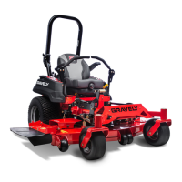
Identifies and describes key controls and features of the unit.
Step-by-step instructions for safely refueling the unit.
Schedule and procedure for lubricating pivot points and fittings.
Procedure for checking and maintaining the hydraulic fluid level.
Instructions for adjusting the tension of the hydro pump belt.
Procedure to correct steering creep by adjusting neutral position.
Steps to align T-bar control levers for proper neutral positioning.
Recommended tire pressure for front and rear tires.
Methods for adjusting tire pressure and lever orientation.
Steps for adjusting deck level front-to-rear and side-to-side.
Procedure for setting the correct tension on the mower belts.
Chart for diagnosing engine problems with causes and actions.
Daily procedure for checking engine oil level.
Guidance on replacing the oil filter during maintenance.
Information on the type and maintenance of the air cleaner element.
Procedure for inspecting and replacing spark plugs.
Step-by-step guide for removing and reinstalling the engine.
Inspection of radiator hoses for wear and damage.
Checking the radiator and cap for dirt, damage, and proper sealing.
Inspection of fan blades, belt condition, and tension.
Recommendation for coolant replacement intervals by authorized dealers.
Detailed procedure for replacing mower belts.
Safety and procedure for checking, sharpening, and balancing mower blades.
Procedure for disassembling, cleaning, and greasing mower deck rollers.
Specific instructions for mower removal and spindle service.
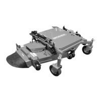
Instructions for removing the mower deck assembly.
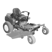
Procedure for removing the mower frame assembly.
Steps to inspect and replace caster bushings.
Instructions for removing and replacing wheel axles.
Procedure for inspecting and replacing lift linkage bushings.
General information about the mower lift hydraulic system components.
Procedure for adjusting steering rod and neutral weldment.
Chart for diagnosing hydro transmission issues.
Steps to replace the hydro pump drive belt.
Procedure for removing the PTO clutch assembly.
Steps for servicing PTO clutch bearings.
Reassembly procedure for the PTO clutch.
Instructions for removing and inspecting the idler pulley.
Procedure for removing wheels and hubs.
Steps for installing wheels and hubs correctly.
Chart for diagnosing fuel system problems.
Explanation of the impulse-style fuel pump operation.
Procedure for addressing fuel system contamination.
Steps for running the unit after hydraulic maintenance.
Information on hydraulic pressure lines and checks.
Procedure for replacing the hydraulic system filter.
Safety and procedure for disconnecting/connecting hydraulic hoses.
Steps for removing and reinstalling the hydraulic tank.
Procedure for servicing the hydraulic oil cooler.
Detailed steps for removing the hydraulic pump.
Guide for using seal kits to overhaul the hydraulic pump.
Procedure for replacing O-rings on check valve plugs and bypass valves.
Instructions for replacing lip-type shaft seals on pumps.
Steps for removing and replacing hydraulic motors.
Lists and describes specialized tools for electrical repair.
Explains basic electrical measurements and meter types.
Safety precautions and first aid for battery handling.
Procedure for charging the battery using the unit or a charger.
Explains switch types and testing procedures for continuity.
Describes operation and function of solenoids and relays.
Basic troubleshooting for lighting system issues.
Explanation of fuse function and replacement procedures.
Describes function and testing of diodes and rectifiers.
Explanation and testing of the electric clutch operation.
Procedure for checking PTO clutch coil resistance and current draw.
Visual representations of switch and relay connections.
Installation checkout and electrical checks for specific models.
Installation checkout and electrical checks for specific models.
| Brand | Gravely |
|---|---|
| Model | Promaster 100 |
| Category | Lawn Mower |
| Language | English |