Do you have a question about the Gravely Promaster 400 and is the answer not in the manual?
Explains the purpose and use of the service manual for unit maintenance and repair.
Guidelines for ordering parts and making service inquiries, referencing unit serial numbers.
Importance of warranty registration card for warranty activation and claims.
Warning against using non-Gravely parts and potential warranty voidance.
Gravely reserves the right to make product changes without prior notice.
Types of communications from Gravely Technical Service (Letters, Bulletins, etc.).
Explains safety alert symbols (Attention, Danger, Warning, Caution) and their meanings.
Defines DANGER, WARNING, and CAUTION signal words and their implications.
Explains NOTE and IMPORTANT notations used in the manual for clarity.
Emphasizes safe working practices, awareness of hazards, and adherence to local laws.
Stresses the importance of operator training for new users and loaned/rented units.
Details pre-work preparation for efficient and safe service repairs, including workspace and tools.
Guidelines for safely positioning the unit for maintenance using jack stands or blocks.
Instructions for cleaning and storing the unit to prevent rust and damage.
Comprehensive safety rules covering inspection, work area, unit operation, slopes, and personal safety.
Instructions for cleaning the unit after use or before storage to maintain condition.
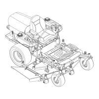
Identifies and describes the main controls and features of the unit with a diagram.
Step-by-step guide for safely adding fuel to the tank, including precautions.
Details lubrication points, intervals, and types of grease/oil for various components.
How to adjust the transmission neutral if the unit creeps when not in gear.
Guidance on checking tire pressure and ensuring proper wheel alignment.
Steps for adjusting the direction control pedal for comfortable and safe operation.
Instructions for daily inspection, service, and adjustment of the brake system for effective stopping.
Procedure for checking and adjusting the PTO clutch engagement.
Guide to diagnose and correct common engine problems using a systematic troubleshooting key.
Daily procedure for checking engine oil level and adding oil if needed.
Steps for changing engine oil and filter at specified intervals for engine health.
Information on checking and maintaining engine coolant levels and antifreeze.
Detailed steps for safely disconnecting and removing the engine from the unit.
Step-by-step guide for installing the engine back into the unit, including connections.
Visual representation of the hydraulic system for the drive train components.
Procedure to prime the transmission after oil changes to prevent internal damage.
Importance of keeping transmission cooling fins clean to prevent overheating.
Schedule and procedure for changing the transmission oil filter and oil.
Steps for removing the flywheel and PTO drive shafts from the transmission.
Flowchart to diagnose and resolve transmission power loss or operational issues.
Procedure for checking transmission implement pressure using a gauge.
Detailed instructions for removing the Sunstrand transmission assembly.
Steps for performing minor repairs on the Sunstrand transmission charge pump.
Procedure for major disassembly and repair of the Sunstrand transmission components.
Steps for installing the Sunstrand transmission back into the unit, including connections.
Table listing causes and remedies for transaxle shifting and noise issues.
Procedure for removing the transaxle from the unit, including disconnecting linkages.
Steps for repairing the transaxle, including axle bearing replacement and housing procedures.
Steps for installing the transaxle back into the unit, ensuring proper alignment.
Procedure for removing the PTO gearbox assembly from the unit.
Steps for disassembling and repairing the PTO gearbox.
Steps for installing the PTO gearbox, including fluid service.
Diagram illustrating the power steering hydraulic system and component layout.
Guide to diagnose and fix common power steering problems like wandering or wheel turning issues.
Notes on proper handling of hydraulic hoses during maintenance to prevent damage.
Steps for removing the steering box unit from the tractor.
Steps for installing the steering box unit, including hose connections.
Procedure for removing the steering cylinder from the unit.
Procedure for installing the steering cylinder, ensuring proper ram orientation.
Refers to wheel alignment section for proper tie rod lengths and toe-in.
Diagram showing the hydraulic system for the lift mechanism, including components and flow.
Guide to diagnose and fix issues with the hydraulic lift system, like deck not raising.
Notes on proper handling of hydraulic hoses for the lift system, connections, and sealing.
Steps for removing the hydraulic lift valve from the unit.
Steps for installing the hydraulic lift valve, including hose and linkage connections.
Procedure for adjusting the hydraulic valve pressure for proper lift operation.
Steps for removing the hydraulic lift cylinder from the unit.
Steps for installing the hydraulic lift cylinder, ensuring correct orientation.
Recommendation regarding adjustments or repairs to the fuel injector pump by authorized facilities.
Procedure for priming the fuel system to ensure fuel delivery to the engine.
Precautions and steps for dealing with fuel system contamination (dirt, water).
Safety precautions and procedures for draining, removing, and installing the fuel tank.
Lists and describes specialized tools needed for electrical repair work, like multimeters and pliers.
Explains basic electrical measurements (voltage, current, resistance) and the use of multimeters.
Instructions for battery setup, electrolyte addition, charging, maintenance, and jump starting.
Explains the function of switches (NO/NC) and how to test them using an ohmmeter.
Describes the operation and testing of solenoids and relays in electrical circuits.
Troubleshooting simple lighting circuits, checking bulbs, fuses, and wiring.
Explains the function of fuses as protective devices and how to test them.
Explains diodes and rectifiers, their function, and how to check them.
Procedures for checking ignition switch, relays, and time delay components.
Diagrams showing electrical component connections and continuity states for switches and relays.
Wiring diagram for Promaster 400, 30-H models.
Wiring diagram for Promaster 400, 22-H models.
Wiring diagram for Model 989057, 306.
Diagram of the hydraulic system for four-wheel drive assist, showing component connections.
Wiring schematic for the four-wheel drive assist system, detailing connections.
Notes on proper handling of hydraulic hoses for the four-wheel drive assist system during maintenance.
Steps for removing the four-wheel drive assist hydraulic manifold.
Steps for installing the four-wheel drive assist hydraulic manifold, including solenoid connections.
Procedure for removing the wheel motor from the axle caster.
Procedure for installing the wheel motor onto the axle caster.
Functional check procedure for the F/W/A toggle switch in various positions.
Adjustment procedure for the reverse safety switch to ensure proper operation.
Information for ordering parts for the mower deck, referencing model and serial numbers.
Table of specifications including cut width, height, construction, and dimensions for mower decks.
Steps for installing and removing the mower deck from the tractor unit.
Lubrication points, intervals for fittings, and gearbox oil check procedures.
Procedure for adjusting the mower deck cutting height using adjustment weldments.
Instructions for cleaning and storing the mower deck to protect its components.
Steps for repairing greasable spindle shafts, bearings, and seals.
| Brand | Gravely |
|---|---|
| Model | Promaster 400 |
| Category | Lawn Mower |
| Language | English |