6 - 35
6.15 TRANSAXLE INSTALLATION
1. Use a jack and raise the transaxle into place.
Install the four spacers and apply loctite to the four
transaxle to frame mounting bolts and start them
into the transaxle.
2. Apply loctite and start the four bolts into the
transaxle at the transaxle plate.
3. Tighten the four bolts at the frame first, then the
four bolts at the transaxle plate.
4. Install the pivot bracket weldments using loctite on
bolts.
5. Install the lift arm weldments and connect the
hydraulic lift cylinders.
6. Connect the brake rods at the cam lever arms and
install the wheel assemblies.
7. Jack the unit.
8. Connect the speed shifter and differential lock rods
at the transaxle.
9. Install the transmission. Connect the hydraulic
reservoir supply hose.
10.Service the transmission and transaxle with clean
fresh oil.
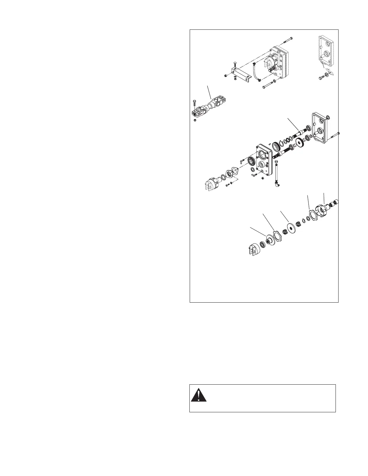
6.16 PTO GEARBOX REMOVAL
NOTE: Position the PTO lever in the off position prior to
performing maintenance.
1. Remove the mower attachment. Refer to Mower
section.
2. Loosen the PTO U-joint assembly at the PTO.
3. Remove the PTO spring from the PTO trunnion by
removing the left side bushing nut. See Figure 38.
4. Remove the PTO clutch assembly. Note the
orientation of the wave springs and clutch disc.
5. Remove the three PTO gearbox mounting bolts
and lift the gearbox away from unit.
CAUTION: The PTO gearbox is heavy, use
caution when removing the three mounting
bolts.
1
2
3
4
5
6
4
Figure 46
1. PTO U-Joint Assembly
2. PTO Input Shaft
(Upper)
3. PTO Clutch Hub
4. Clutch Disc
5. Clutch Plate
6. Clutch Actuating Hub