S
Susan MaynardJul 30, 2025
What to do if my Gravely Lawn Mower will not crank?
- JJohn CoxJul 30, 2025
If your Gravely Lawn Mower will not crank, the suggested solution is to charge the battery or replace it.
What to do if my Gravely Lawn Mower will not crank?
If your Gravely Lawn Mower will not crank, the suggested solution is to charge the battery or replace it.
Describes the purpose, scope, and usage of the service manual.
Explains how to order parts and identify unit/engine serial numbers.
Lists types of technical information communications from Gravely to dealers.
Defines DANGER, WARNING, and CAUTION signal words and their hazard levels.
Outlines general safety rules for operation and work area.
Describes how to safely position the unit for maintenance tasks.
Safety precautions and handling guidelines for the unit's battery.
Instructions for cleaning grass, dirt, and debris from the unit.
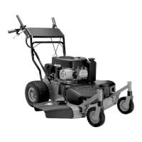
Identifies and illustrates the main controls of the Pro 100 and Pro 150 models.
Provides instructions and safety warnings for refueling the unit.
Explains the operation of the steering levers for unit control.
Provides procedures for adjusting steering levers and brakes.
Outlines the procedure for adjusting the PTO clutch on recoil start models.
Details how to adjust the roller chain between transmission and jackshaft.
Provides a chart for diagnosing and correcting engine problems with a troubleshooting key.
Step-by-step procedure for safely removing the engine from the unit.
Explains the function of the operator presence control system for safety.
Guides on diagnosing issues if the unit will not move or mow.
Details the procedure for replacing the transmission belt on models.
Provides steps for safely removing and installing traction belts.
Details the process for replacing the PTO clutch belt on specified models.
Explains how to remove the electric clutch assembly.
Offers a chart for diagnosing and correcting fuel system issues.
Lists specialized tools and supplies required for electrical repair work.
Explains basic electrical measurements and types of multimeters.
Covers battery safety, setup, charging, and maintenance procedures.
Explains switch types (normally open/closed) and how to test them.
Describes the operation and testing of solenoids and relays.
Explains semiconductor devices and methods for testing diodes.
Outlines how to measure PTO clutch coil resistance for diagnosis.
Provides electrical diagnostic steps for Kohler engine models.
Outlines electrical checks specific to Briggs/Stratton engines.
Shows continuity states for electrical components on recoil start models.
Shows continuity states for electrical components on electric start models.
Provides wiring diagrams for specific model numbers.
Presents the wiring diagram for Pro 200 with Briggs & Stratton engine.
Presents the wiring diagram for Pro 200 with Kohler engine.
Illustrates electrical components for specific models.
Illustrates electrical components for other specified models.
| Brand | Gravely |
|---|---|
| Model | Pro 100 |
| Category | Lawn Mower |
| Language | English |