8 - 30
(Electric/Hydraulic Pump)
Problem-solving Chart
Electric/Hydraulic Pump Removal
1. Disconnect black ground wire at frame.
2. Remove switch from dash. Leave the three leads
connected to switch.
3. Clean hydraulic fittings and mark hoses to insure
proper routing at time of pump installation.
4. Disconnect hydraulic hoses from pump.
NOTE: Support electric/hydraulic lift pump when
removing mounting bolts.
5. Remove the two mounting bolts and lift pump out
of unit.
6. Drain hydraulic fluid through reservoir cap.
7. Repair as needed.
Electric Hydraulic Pump Installation
1. Install pump with the two mounting bolts.
2. Reconnect hydraulic hoses.
3. Install switch into dash with green terminal to the
top and blue terminal to the bottom.
4. Reconnect black ground wire to frame.
5. Remove cap and service hydraulic reservoir with
Dextron II or Dextron III to full line. Install cap.
6. Reconnect battery, negative terminal first.
Electric/Hydraulic Pump Switch Replacement
1. Remove switch from dash and disconnect the
three leads.
2. The switch can only be installed one way. Check
orientation of switch for proper lead hookup.
3. Connect the three leads to the switch—green - top,
red - middle, and blue - bottom.
4. Install switch into dash. Reconnect the battery,
negative terminal first and check operation of
switch.
Hydraulic Hose Removal
1. Clean hydraulic fittings prior to removing hoses.
2. Disconnect hydraulic hose(s) from cylinder end
first.
3. Disconnect hydraulic hose(s) from pump end.
4. Replace hoses as needed.
Hydraulic Hose Installation
1. Connect hydraulic hose(s) to pump first.
2. Connect hydraulic hose(s) to cylinder.
3. Connect battery, negative terminal first.
4. Cycle unit up and down a few times to bleed the
system.
5. Add Dextron II or Dextron III to the full line on the
reservoir if servicing is needed.
Hydraulic Cylinder Removal
1. Clean hydraulic fittings prior to removing hydraulic
hoses.
2. Disconnect hydraulic hoses. Note orientation of
hydraulic hoses.
3. Disconnect cylinder from mower lift weldment.
Note which hole cylinder is connected to.
4. Remove the left side retaining ring from the
hydraulic cylinder shaft.
5. Support hydraulic cylinder and slide hydraulic
cylinder shaft out on the right side far enough to
clear cylinder.
6. Remove cylinder from tractor.
Hydraulic Cylinder Installation
NOTE: Hydraulic ports for fittings need to be facing up.
1. Slide cylinder shaft through hydraulic cylinder and
out through the left side of tractor frame.
2. Install left side retaining ring on cylinder shaft.
CAUTION: Remove attachment from tractor
or disconnect attachment at mower lift arm
prior to working on lift system. Replace
hydraulic fluid after any maintenance has
been performed on the lift system.
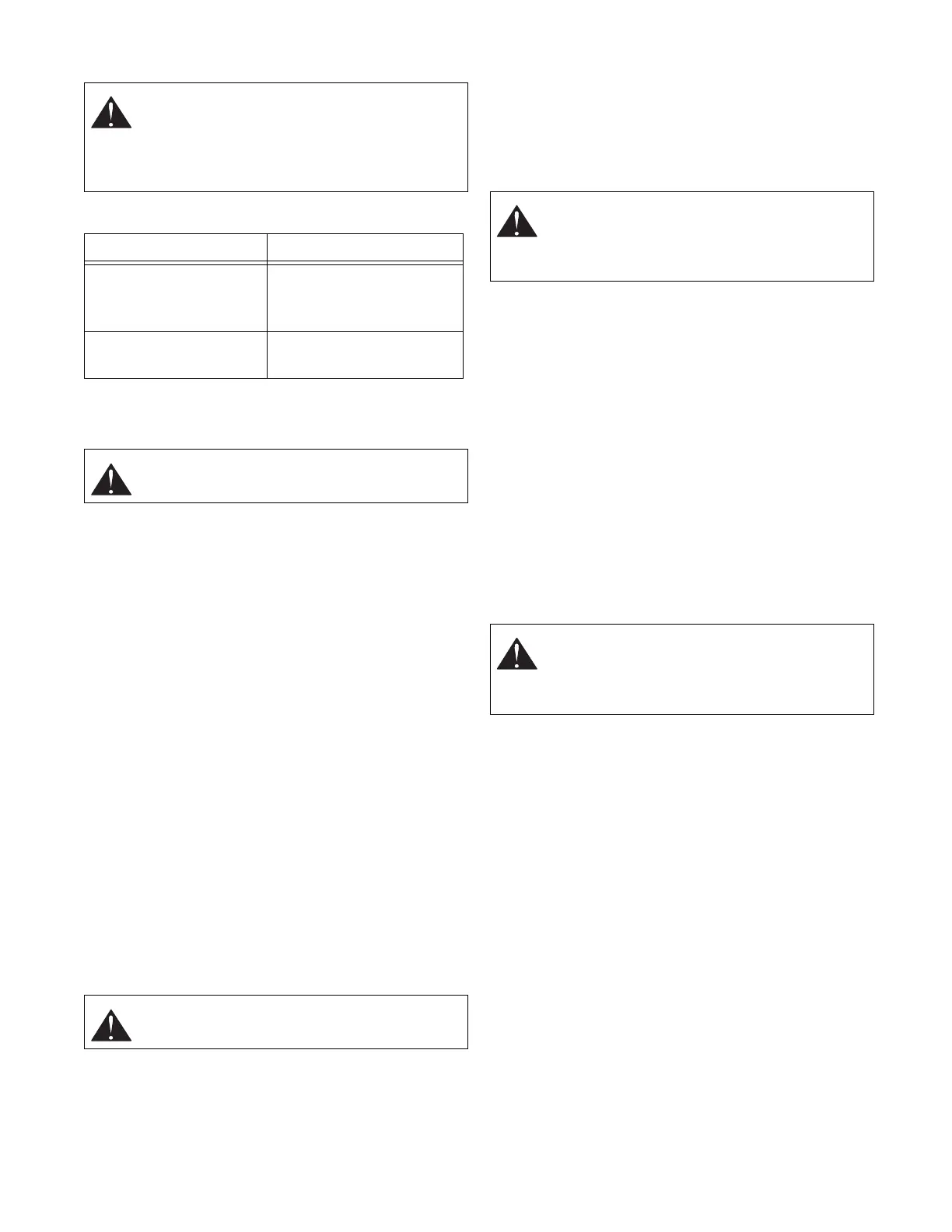
Observation Possible Cause
Attachment will not raise. Discharged battery.
Loose connection to
solenoid or ground.
Attachment raises slowly. Hydraulic lines routed
incorrectly.
CAUTION: Disconnect battery negative
terminal first.
CAUTION: Disconnect battery negative
terminal first.
CAUTION: When hydraulic pump is operated
hydraulic fluid is under high pressure. To
avoid injury disconnect battery (negative
terminal first) prior to working on hoses.
CAUTION: When hydraulic pump is operated
hydraulic fluid is under high pressure. To
avoid injury disconnect battery (negative
terminal first) prior to working on hoses.