GB - 28
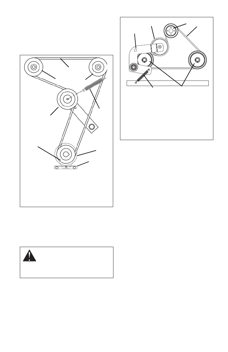
Installation (Figure 22)
1. Install new hydro pump belt by
positioning belt on sheaves. Put belt
onto right hand hydrostat sheave last.
2. Replace clutch anchor.
3. Install PTO belt on electric clutch (see
PTO BELT REMOVAL on page 26).
TRANSMISSION BELT REMOVAL
(992156, 160)
Removal (Figure 23)
1. Place unit in the service position (see
SERVICE POSITION on page 20).
2. While pulling idler pulley away from unit,
remove transmission belt from idler
pulley.
3. Slowly release the tension on idler pulley
until all the tension is removed from
spring.
4. Remove transmission belt from
crankshaft pulley and two hydrostatic
pump pulleys.
Installation (Figure 23)
1. Install the new transmission belt on two
hydrostatic pump pulleys and crankshaft
pulley.
2. While pulling idler pulley away from unit,
install transmission belt on idler pulley.
3. Slowly release the tension until idler
pulley is firmly against transmission belt.
CAUTION: Use care when
releasing idler spring tension.
Keep body parts well away from
idler when performing this
operation.
OF1631
1. Right Hand
Hydrostat
2. Hydro Belt
3. Left Hand
Hydrostat
4. Spring
5. Clutch
6. Clutch Anchor
7. Engine
Sheave
8. Idler
Figure 22
1
2
3
4
5
6
7
8
Figure 23
OF3300
1
6
2
4
5
3
1. Square Hole
2. Idler Pulley
3. Crankshaft Pulley
4. Transmission Belt
5. Hydrostatic Pump Pulleys
6. Spring