GB - 32
Changing Hydraulic Oil and Filter
NOTE: Change the hydraulic oil filter and
hydraulic oil every 500 hours. Use Mobil 1
Extended Performance 15W50 Synthetic Oil
or equivalent for best component life (p/n
00057100).
NOTE: When changing the oil, only about 1.5
quarts (1.4 liters) will drain. The rest of the oil
will remain in the pumps and motors.
1. Clean around dipstick cap and dipstick.
Remove dipstick.
2. Place container under oil filter to catch
oil.
3. Remove oil filter.
4. Allow tank to drain.
5. Lubricate rubber gasket on new oil filter
with clean hydraulic oil.
6. Spin new oil filter onto filter housing until
it makes contact. Tighten oil filter
another 1/2 turn.
7. Add new oil to the oil tank. It will take
about 1.5 quarts (1.4 liters). Use Mobil 1
Extended Performance 15W50
Synthetic Oil or equivalent for best pump
and wheel motor life.
8. Check hydraulic oil level.
9. Properly dispose of waste oil.
COOLING SYSTEM
(992152, 156, 159, 160, 176)
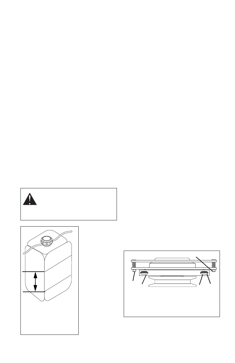
Checking Coolant Level
Check coolant
level when
engine is cold.
Check coolant
level at overflow
reservoir.
1. Place unit in
the service
position (see
SERVICE
POSITION on
page 20).
2.Check
coolant
reservoir.
Coolant should
be between the
low and full
marks with
engine cold.
3. If coolant is below the low mark, remove
cap, and add coolant to the full mark.
Refer to Engine Manual for the correct
type of coolant.
Changing Coolant
Refer to Engine Manual for the correct
procedure on when and how to change the
coolant.
CLUTCH ADJUSTMENT
(Figure 29)
If clutch fails to engage or disengage properly
or begins to make abnormal noise, check the
air gap adjustment at the three inspection
slots.
To check:
1. Stop engine, remove key and wait for all
hot parts to cool.
2. Measure the air gap between the
armature and the rotor.
Minimum: A .016" feeler gauge should
slide between armature and rotor with
slight contact.
Maximum: A .020" feeler gauge should
slide between armature and rotor with
slight contact.
3. Repeat for each inspection slot.
To adjust:
1. If necessary, loosen gap adjustment
nuts until a .016" feeler gauge fits
between armature and rotor.
2. Slide a .020" feeler gauge between
armature and rotor.
3. Tighten gap adjustment nut until there is
slight contact on feeler gauge.
4. Repeat steps 1 – 3 at each inspection
slot.
NOTE: Adjust air gap as evenly as possible.
5. Start unit, engage and disengage PTO.
6. Shut off unit.
7. Recheck air gap and adjust if needed.
WARNING: To avoid personal
injury DO NOT remove radiator
cap when engine is hot. Check
coolant level at coolant reservoir,
not at radiator.
FULL
LO
W
OF3226
2
1
1. Operating Range
2. Full
3. Low
3
Figure 28
Figure 28
1. Armature
2. Rotor
3. Inspection Slot
4. Gap Adjustment
Nut
1
2
3
4
4
Figure 29