EasyManua.ls Logo

Gray WPLS-160 - User Manual

Default Icon
2 pages
Print Icon
To Next Page IconTo Next Page
Loading...
Page 1 of 2
DN082417 © 2017 Gray Manufacturing Company, Inc. 670-90373 Rev. B
Each Gray WPLS-160 lift unit is equipped with two mechanically locking down stops. These down stops are
retracted during lowering using 12-volt solenoids. The following instructions are the proper replacement
procedures for the Down Stop Solenoid in Gray’s Wireless Portable Lift System, Model WPLS-160. Please
follow the steps outlined to properly install the down stop solenoid. If you have any questions during this
process, please contact Gray Customer Service immediately.
Check to make sure that all of the following items are included in your kit prior to proceeding:
1. Open the right hand cover. Lift the WPLS-160 by raising up on the manual override toggle and
depressing the raise button to raise the lift carriage 15-inches off the floor. See Figure 1.
Figure 1 Figure 2
2. Open the left hand cover and turn the Main Power Switch to the OFF position. See Figure 2. This should
be done before any work is performed on the lift.
3. Open the front cover and prop it up with the support rod. See Figure 3.
Figure 3
Item
Qty
Part Number Description
1 1 936-04174 Solenoid, Encapsulated, 12 VDC
2 4 204-00701 Washer, Flat, #8, Type A
3 4 203-00501 Nut, Hex, #4 – 40 UNC, Self Locking
4 4 202-00701 Screw, Pan Head, #8 -32 UNC X .750 Long
Professional Service Equipment
3501 S. Leonard Rd.
P.O. Box 728
St. Joseph, Missouri 64502
U.S.A.
Toll Free: (800) 821-7320
Phone: (816) 233-6121
Fax: (816) 233-7251
Email: parts@grayusa.com
www.grayusa.com
WPLS - 160
Down Stop Solenoid
Replacement
Question and Answer IconNeed help?

Do you have a question about the Gray WPLS-160 and is the answer not in the manual?

Summary

WPLS - 160 Down Stop Solenoid Replacement

Prepare Lift for Service

Lift carriage 15 inches using manual override toggle and raise button.

Disable and Access Components

Turn power OFF, open left cover, and prop open front cover.

Remove and Replace Solenoid

Disconnect wires, remove old solenoid, install new one with hardware.

Test and Finalize Installation

Reconnect wires, check plunger movement, restore power, and test lift.

Overview

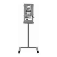
The Gray WPLS-160 is a wireless portable lift system designed for professional service environments. This document specifically details the replacement procedure for the Down Stop Solenoid, a critical component in the lift's safety and operation.

Function Description:

The WPLS-160 lift unit is equipped with two mechanically locking down stops. These down stops serve as a safety mechanism, preventing unintended lowering of the lift carriage. During the lowering process, these down stops are retracted by 12-volt solenoids. The solenoids are electromechanical devices that, when energized, pull a plunger to disengage the mechanical lock, allowing the lift to descend. Proper functioning of these solenoids is essential for safe and controlled operation of the lift.

Important Technical Specifications:

The replacement kit for the down stop solenoid includes several key components:

  • Solenoid, Encapsulated, 12 VDC (Part Number: 936-04174): This is the core component, a 12-volt direct current solenoid designed to retract the down stops. The "encapsulated" designation suggests it's sealed for durability and protection against environmental factors, which is important in a workshop setting.
  • Washer, Flat, #8, Type A (Part Number: 204-00701): Four of these washers are included, likely used to provide a smooth bearing surface and distribute the load when securing the solenoid.
  • Nut, Hex, #4 – 40 UNC, Self Locking (Part Number: 203-00501): Four self-locking hex nuts are provided. Self-locking nuts are crucial in applications subject to vibration, as they resist loosening over time, ensuring the solenoid remains securely fastened. The #4-40 UNC specification refers to the thread size and type.
  • Screw, Pan Head, #8 -32 UNC X .750 Long (Part Number: 202-00701): Four pan head screws are included. Pan head screws offer a good bearing surface and are commonly used for attaching components. The #8-32 UNC x .750 long specification indicates the thread size, type, and length of the screw.

The lift operates on a 12-volt DC system for the solenoid, indicating it's likely powered by a battery system, typical for portable equipment.

Usage Features:

The WPLS-160 is a wireless portable lift system, suggesting flexibility in its deployment within a service environment without being tethered by power cords for its primary movement. The down stop mechanism is integral to its safe operation, ensuring that the lift carriage is securely held at desired heights. The system incorporates a manual override toggle and raise/lower buttons for operation. The need to raise the lift carriage 15 inches off the floor for solenoid replacement indicates a specific operational state required for maintenance access. The presence of a Main Power Switch (OFF/ON) emphasizes safety protocols, requiring the power to be off before any maintenance work is performed. The system also includes a needle valve, which must be opened to lower the lift and then closed for proper operation, highlighting a hydraulic or pneumatic control aspect.

Maintenance Features:

The document provides a detailed, step-by-step guide for replacing the down stop solenoid, emphasizing ease of maintenance for trained personnel.

  1. Access: The process begins by opening the right-hand cover and raising the lift carriage to a specific height (15 inches) to provide access to the solenoid. This suggests a design that facilitates component access for servicing.
  2. Safety First: A crucial step is to open the left-hand cover and turn the Main Power Switch to the OFF position before any work, underscoring the importance of electrical safety during maintenance.
  3. Component Access: Opening the front cover and propping it up with a support rod further enhances access to internal components.
  4. Disconnection: The red and black wire leads connected to the solenoid must be removed, indicating a simple electrical connection.
  5. Removal: The solenoid is secured by four screws and washers, which are to be removed. The instructions specifically highlight the presence of a spring and washer over the plunger, emphasizing the need to note their orientation for correct re-installation. This attention to detail in the instructions helps prevent common assembly errors.
  6. Re-assembly: The guide provides clear instructions for inserting the washer and spring onto the plunger, specifying the orientation of the spring (narrow side touching the washer, wider side contacting the solenoid). This precision is vital for the solenoid's proper mechanical function.
  7. Attachment and Alignment: The new solenoid is attached using the same screws and washers, with instructions to orient the solenoid terminal up and use the same slots for re-attaching. A critical step involves manually retracting the down stop unit and sliding the solenoid forward until it is flush or slightly protruding from the edge of the down stop bracket. This alignment is key to ensuring the down stop engages and disengages correctly.
  8. Electrical Connection: Reconnecting the red and black wire leads is a straightforward step.
  9. Functionality Check: After installation, a crucial maintenance step is to check the solenoid by depressing the down stop back and forth to ensure free plunger movement. If movement is restricted, the instructions advise slightly loosening the screws and re-aligning the solenoid, demonstrating a built-in troubleshooting step for installers.
  10. System Re-activation: The process concludes with turning the Master Power Switch back to ON, closing covers, and lowering the lift using the manual override and needle valve, with a reminder to close the needle valve for proper operation.

The availability of a detailed manual, contact information for customer service (phone and email), and a website indicates a strong commitment to product support and maintainability. The inclusion of part numbers for all components in the kit simplifies ordering replacements.

Gray WPLS-160 Specifications

General IconGeneral
BrandGray
ModelWPLS-160
CategoryIndustrial Equipment
LanguageEnglish

Related product manuals