Connect
the other encl to the solder lLrg
on the
BLACK
(neeative)
terminal
Jrost.
-l
il. Cut bc.,th leacjs
of
resistor
R2,
E20
ohnr:.
(gray-red-
brolvrr), to
i+-inch
lcngth.
Cut lr,vo
ltieces
of black
spaghetti iLrbing,
each
1,'!
-inch
Iength. Slip one
piece
or",er cach of ihe resistor learJs.
Connect ont.l
lead
to
lLrg
C oi the
potentiomete
r
and the
r.,iirei'
lead
to
iL-ig i\
oi tlre ierminal
stl.ip.
(R.efer
to
Fis 7.\
-1 -1
.
Cut both ieads
of zener ciiocle
CR3 to %-inch
length.
Connect the
CATIJODE
Iead
(lead
nearest
the
ccloi"band, as
shor,vn
in Fig.6)
to
IuE
C of the
potentionre
Ier ancl solcJer
(solder-2).
Connect the
ANODE
lead to lug A
oi the
potentionreter
ancl
solder
(solder-3).
(Rcfer
to
Fig.
7.)
12.
Connect the
ANODE
lead
of diode CR1 to
lug E
: ,
-I.ECTOR
FIG. 4
of the transformer
and solder
(solder-1).
(Refer
to
Figs. 6 and 7.) lnsert
the CATHODE Iead
(lead
near-
est
the color
band)
through lug B
of
the
terminal
slrip and connecl
it to
lug A
as shown in
Fig.7.
13.
Cut both leads of
diode CnZ to
%-inch
length.
Connect the ANODE lead
to lug
C
of the
trans-
former
and solder
(solder--l).
Connect the
CATH-
ODE lead to lug B
of the terminal strip.
14.
Cut both leads
of capacitor
C2, .02
p,.F,
to
3/c-inch
length.
Connect
one lead to Iug B
of the terminal
strip
and solder
(solder-3).
Connect the other lead
to lug D
of
the
terminal strip.
15.
Cut both leads
of resistor R3, 1K ohms
(brown-
black-red),
to
1/z-inch
length.
Connect one
lead
to
Iug
C of
the terminal strip and
the other
lead
to
lLrg D
of the.tc,r.nrin.tl
slrip.
-1[r.
CLrt both leads
of
capacitor
C3,
470
uF, to
%-inch
length
Connect
the
POSII
IVE lead
to
lug
D of the
terminal strip
and solder
(solcler'5)
Connect the
other lead
to the solder lug
on the BLACK terminal
po5t,
as shorvn inFig 7,
and solder(solder-2)
l7
CLrt
both leads
of capacitor
C1,100 uF, to %-inch
Iength
Connect the POSITIVE iead
to
lug
A of the
terrnrnal strrp and
solder
(solder-4)
Connect the
other
lead
to lug
C
ot the
terminal strip and solder
{'older-2r
tRpter
to I ig 7
t
lf breadboard
rvas
constructed,
omit step-1
B
18.
Scpar.rte the tu,o le;rd,s
of
thc
Iine corcl ior 11l:
-
inches ironr llrc
encl.
StriJr
r,+
-inc.h
oi insLt l.rti<tn
ironr
the cncl of
ltoth
lcacls Tu.,ist together
the
sLrancJs
n'itlrin
cac.h
Icacl
.rrrrJ tin.
iReier
to
Fig
B.)
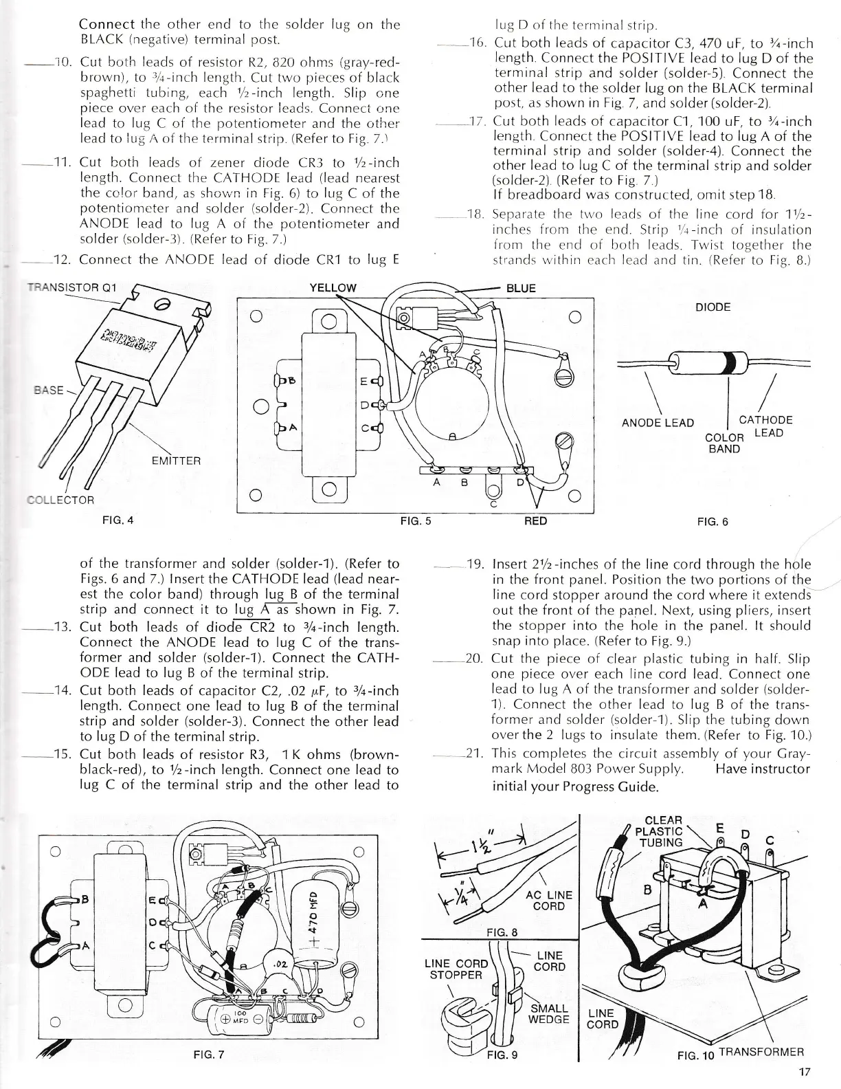
DIODE
FIG. 5
EMITTER
'G
\
--r-
/
\'l/
ANODE LEAD
CATHODE
COLOR
BAND
LEAD
FIG.6
19. lnsert
2%-inches
of the
Iine
cord through the hoie
in
the
f ront panel. Position
the two
portions
of the
Iine
cord
stopper around the cord where
it
extends
out the front of
the
panel.
Next,
using
pliers,
insert
the stopper into
the
hole in
the
panel.
lt
should
snap into place.
(Refer
to
Fig.
9.)
20.
Cut the
piece
of clear
plastic
tubing
in
half. Slip
one
piece
over each Iine
cord lead. Connect
one
lead
to lug A
of the transformer and
solder
(solder-
1).
Connect
tl-re other lead to lug B
of the trans-
former
ancl solder
(solder-l
).
Slip
the
tubing do,"r,n
over the 2 lr-rgs
to
insulate them.
(Refer
to Fig.
10.)
21. This
conrpletes the
circuit assembly of
vour
Cray-
mark
,\loclel
803
Pou,er
Supply. Have instructor
initial your
Progress
Cuide.
FIG. B
,.......-
LINE
LINE
CORD
STOPPER
TRANSFORMER
C
f n l\-tl]ol
E=a(
t\ C
 Loading...