CLEAR
PLASTIC
TUBING
-
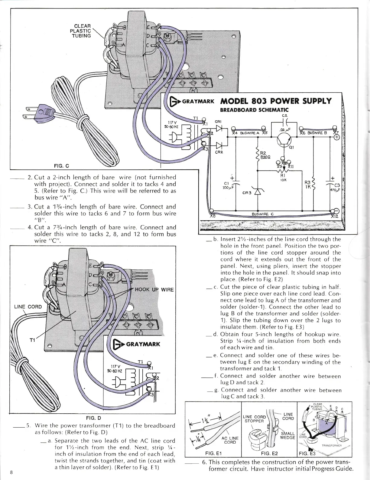
3.
Cut a
13/t-inch length
of bare wire. Connect
solder this wire to tacks 6 and 7 to form bus
D
4. Cut a
73/+-inch
length
of bare
wire.
Connect
solder this wire to tacks 2,
B, and
12
to
lorm
wire
"C".
FIG.
C
2.
Cut
a 2-inch
length
of bare
wire
(not
f
urnished
with
project).
Connect and solder
it
to tacks
4 and
5.
(Refer
to Fig.
C.)
This wire will be referred
to as
bus wire
"A".
$>onavr'ranqUQDEL
8O3
POWER
SUPPLY
117
Y
50-60
Hz
and
wire
and
bus
BREADBOARD SCHEMATIC
a--g
Y4 BUSWIREA X5
a,^F
irrl#
jr,,,",,;,,;#
;i:i:i.,i*,iiijit,.?t*i+.;ttli$
*_
b lnsert
21./t
-inches
of
the
line cord
through the
hole in
the
front
panel
Position
the two
por-
tions of the
line
cord stopper around
the
cord
where it
extends out
the
front
of
the
panel.
Next,
r-rsing
pliers,
insert
the
stopper
into
the
hole in
the
panel
lt should snap into
place.
(Refer
to
Fig E2)
-
c
Cut the
piece
of clear
plastic
tubing
in
half
Slip one
piece
over
each line
cord
lead.
Con-
nect
one
lead
to
lug A
of the transf ormer and
solder
(solder-'1
).
Connect
the other
iead
to
Iug
B of
the transformer and solder
(solder-
1).
Slip the tubing down over
the
2 lugs
to
insulate
them
(Refer
to
Fig. E3)
-
d.
Obtain
four
5-inch
lengths
of hookup n,ire
Strip
l/a-inch
of insulation from
both ends
of each wire
and
tin.
-
e.
Connect and solder
one of
these
wires
be-
tween
lug E
on
the
secondary winding
of
the
transf ormer
and tack 1.
-
f
Connect
and solder
another wire
between
lug
D and
tack
2.
-
g
Connect and
solder
another wire
between
lug
C
and
tack 3.
-
6.
This
completes the
construction of the
power
trans-
former circuit.
Have instructor initial ProgressCuide
FIG. D
-
5 Wire
the
power
transformer
(T1)
to the
breadboard
as follows:
(Refer
to
Fie D)
-a.
Separate
the two
leads
of the AC line cord
lor 11h-inch f
rom
the
end. Next, strip
%-
inch
of insulation from
the end of each lead,
twist
the
strands
together,
and
tin
(coat
with
a
thin
layer
of solder)
(Ref
er to
Frg E 1)
til-,.,.
+Eo"cg?D\\\h
ctib
\ dv-
(@51/7ivs::
'a4u
FIG. E2
FIG. E1