PHASE
II
ASSEMBLY
PROCEDURE
CIRCUIT
ASSEMBLY
Do not
solder
any
w'ires
or component leads until instructed
to
do so. After
all
wires
and leads have
been connected to a
particular
lug or terminal, it
should then be soldered.
To
assist
you,
the
word
"solder"
and a
number in
parenthesis
O
will indicate
the
number
of
leads
that are supposed to be
connected
to the lug
at the time it is soldered. Example:
(solder-2)
means
two leads are to
be
soldered to the Iug.
CAUTION: DO
NOT DISTURB MOUNT/NC
OF TRANS/S-
TOR
Q7.
HOWEVER,
tF tT BECOMES
NECESSARy TO Rt-
MOVE
IT,
BE
SURE THE iNSUtAIlNC
WA5I1ERs ARE RE-
PLACED PROPERtY.
Assemble
your project
as follows:
-l
.
Mount potentiometer
R1,
-1
0K ohms, to the front
panel
and
position
the three lugs
as shown
in Fig. 1.
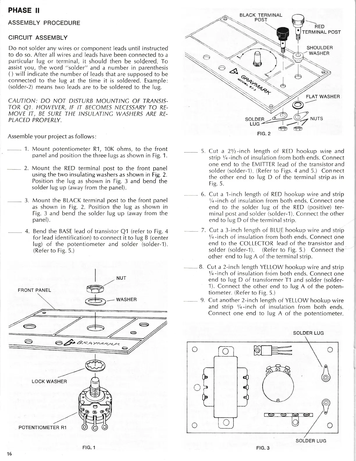
2. Mount
the RED
terminal
post
to the front
panei
using
the two insulating
washers as shown in Fig.2.
Position
the lug
as shown in Fig.3 and
bend
the
solder lug up
(away
{rom
the
panel).
-
3.
Mount
the BLACK terminal
post
to the
front
panel
as shown in Fig.2. Position the
lug
as shown in
Fig.3 and
bend
the
solder
lLrg up
(away
from
the
panel).
4. Bend the
BASE
lead of transistor
Q1
(refer
to
Fig.
4
for lead identificatron)
to
connect it
to
lug B
(center
Iug)
of the
potentiometer
and solder
(solder-1).
(Refer
to
Fig.
5.)
|
-*u,
d
A-.-
ryASHER
/---/
LOCK
WASHER
BLACK TERMINAL
FIG.
2
-
5.
Cut a 2lh-inch length of RED l-rookup wire and
strip
/.r-inch
of insulation from both ends. Connect
one end to
the
E/V1 ITTER
lead of the transistorand
solder
(solder-1).
(Refer
to Figs. 4 and 5.)
Con
nect
the other end
to
lug D
of
the
terminal strip
as in
Fig.5.
6. Cut a 1-inch length
of
RED hookup r'vire and
strip
1,/a-inch
of
insr-r lation from
both
ends. Connect one
end to tl-re
solder
lug
of the
RED
(positive)
ter-
minal
post
and solder
(solder-1).
Connect the other
end to Iug D
of the terminal strip.
7. Cut a 3-inch length
of
BLL.I-E hookup rvire
and strip
%-inch
of
insulation
from both ends. Connect one
end to the
COLLECTOR
lead
of the transistor and
solder
(solder---t). (Refer
to Fig.
5.) Connect the
other
end to
lug
A
of
the termina!
strip.
B.
Cr-rt a 2-inch
length YELLOW
hookup rvire
and strip
%-inch
of
insulation
from
both ends.
Connect one
end to lug D
of transformer T1
and solder
(solder-
1).
Connect
the other
end
to lug
A of the
poten-
tiometer.
(Refer
to Fig.
5.)
-
9. Cut another
2-inch length
of
YELLOW hookup
wire
and
strip
%-inch
of
insulation
from
both ends.
Connect
one
end
to lug A
of the
potentiometer.
SOLDER LUG
m____
\-7
RED
p
re
nvrNar- eosr
t=f-T:
PI-
C
\/il
/\
@
16
POTENTIOMETER R1
FIG. 1
FIG.
3
SOLDER
LUG
FRONT PANEL
).t-[
.-a
SHOULDER
WASHER
FLAT WASHER
SOLDER
LUG
-/l
o