,STRUMENTATION
&
MEASUREMENT
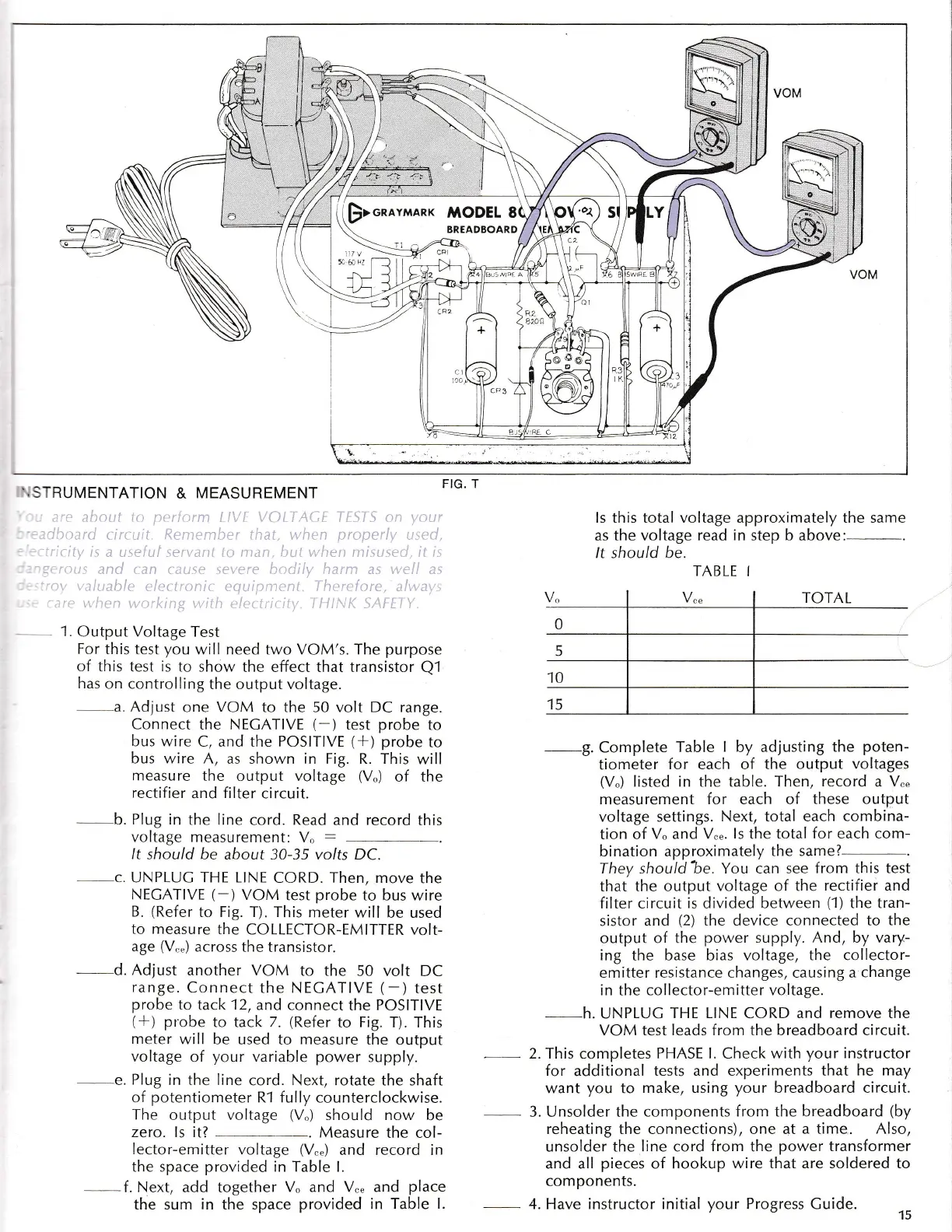
1.
Output Voltage Test
For
this test
you
will need two VOM's. The
purpose
of this test is
to show
the effect that transistor
Q1
has
on controlling
the output voltage.
a. Adjust
one
VOM
to the 50 volt DC range.
Connect
the
NECATIVE
(-)
test
probe
to
bus wire
C, and the
POSITIVE
(*)
probe
to
bus wire A,
as shown
in
Fig. R. This
will
measure the
output voltage
(V")
of the
rectifier
and filter
circuit.
-b
Plug in
the line
cord.
Read
and record
this
voltage measurement:
V.,
:
It should
be about 30-35 volts DC
c.
UNPLUC
THE
LINE
CORD.
Then,
move
the
NECATIVE
(-)
VOM
test
probe
to bus wire
B.
(Refer
to Fig. T). This
meter will
be used
to measure
the
COLLECTOR-EMITTER volt-
age
(V,.")
across the transistor.
-
d Adjust
another VOM
to the 50 volt
DC
range.
Connect
the NECATIVE
(-
)
test
probe
to
tack
12,
and connect
the
POSITIVE
(-l1
probe
to tack
7.
(Refer
to
Fig.
T). This
meter
will be used
to
measure
the output
voltage
of
your
variable
power
supply.
e.
Plug in
the line
cord. Next,
rotate
the shaft
of
potentiometer
R-l fully counterclockwise.
The output voltage
(V.)
should now be
zero. Is it?
-
Measure
the col-
lector-emitter voltage
(V"")
and record in
the space
provided
in Table I.
--,f.
Next,
add
together
V. and V"" and
place
the sum
in
the space
provided in Table I.
-9.
Complete
Table I by adjusting
the
poten-
tiometer
for each of the
output voltages
(V")
listed
in
the
table. Then,
record
a
V""
measurement
for each of
these output
voltage settings. Next,
total each combina-
tion of
V" and V"".
Is
the total
for each com-
bination
approximately
the same?-.
They
should
%e. You can see
from
this
test
that the output
voltage of the
rectifiei
and
filter circuit
is
divided
between
(1)
the tran-
sistor and
(2)
the device connected to
the
output of the
power
supply. And, by vary-
ing
the base bias
voltage, the collector-
emitter
resistance changes, causing a
change
in
the
collector-emitter voltage.
-h.
UNPLUG
THE LINE
CORD
and remove the
VOM
test
leads from the breadboard circuit.
This
completes
PHASE l. Check with
your
instructor
for
additional
tests and experiments that he
may
want
you
to
make,
using
your
breadboard circuit.
Unsolder the components
from the breadboard
(by
reheating the connections), one at a time. Also,
unsolder the
line cord from the
power
transformer
and all
pieces
of hookup
wire that are soldered to
components.
Have instructor initial
your
Progress Guide.
15
ls
this
total voltage
as the voltage
read
It should be.
approximately the same
in
step b above:-.
TABLE
I
__
2.
_3.
_4.
p>onara,ranx
MODEL