VOLTAGE CONTROL
EXPERIENCE
DISCUSSION
In this experience
you
will construct
a variable
voltage
power
supply by adding a
voltage control
circuit to the
b
read
boa
rd.
In
this circuit, transistor
Q1
acts
lil<e
a variable
resistor con-
nected in
series
with
a
"load".
Zener diode CR3
is used as
a bias voltage
reference. That is,
it maintains 16 volts
across
potentiometer R1. The
output
voltage
level is
controlled
by
the amount of
bias voltage on the base of
the transistor.
Potentiometer R-1
controls this
bias voltage.
The
greater
the
bias voltage, the
greater
the or-rtput
voltage.
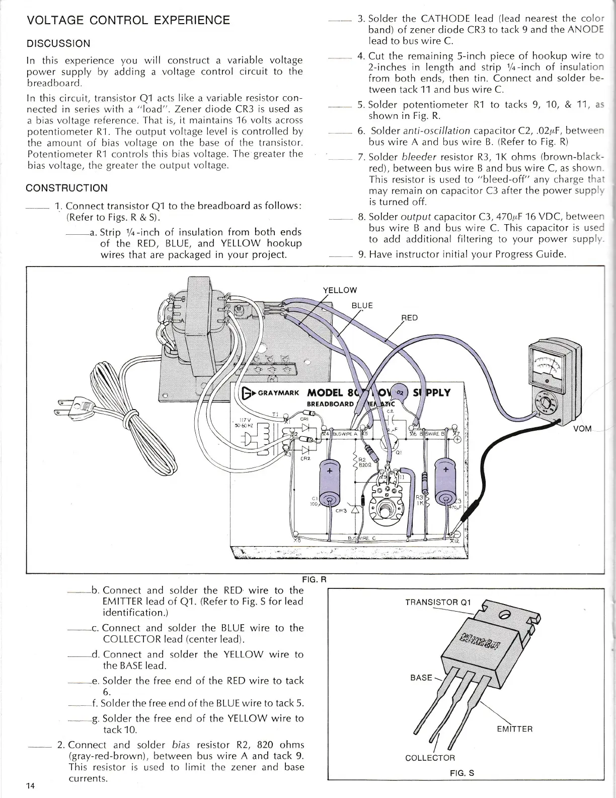
CONSTRUCTION
-
1.
Connect transistor
Ql
to the
breadboard as
follows:
(Refer
to
Figs. R
& S).
a. Strip
1/q-inch
of
insulation from both ends
of the
RED, BLUE, and YELLOW
hookup
wires that are
packaged in
your
project.
Solder the CATHODE
lead
(lead
nearest the
co c'
band) of zener diode CR3 to
tack 9 and the
ANCD:
Iead to bus wire C.
Cut the
remaining
5-inch
piece
of
hookup wire i-
2-inches in Iength
and strip
1/+-inch
of
insulat:c
-
from both ends, then tin. Connect
and solder
be-
tween tack 11 and bus wire C.
-
5. Solder
potentiometer
R-l to tacks 9,
10, &
1-1
,
a..
shown in Fig. R.
6. Solder
anti-oscillation capacito
r
C2,
.02y.F, betrr ee-
bus wire
A
and bus
wire B.
(Refer
to
Fig. R)
7. Solder bleeder resistor
R3, 1K
ohms
(brorvn-blaci:-
red),
betw'een bus
wire B and bus
wire
C,
as sho',',-
This resistor is
used to "bleed-off"
any charge
tl .
-
may remain on capacitor C3 after
the
power supp
is turned
off.
8. Solder output capacitor C3,47O1tF
16 VDC, bett'ee-
bus wire B and bus wire C.
This capacitor
is
use
to
add additional filtering to
your
power
supp"
9. Have
instructor initial
your
Progress
Cuide.
__
3.
_4.
FIG,
R
b.
Connect and solder the
RED
wire to the
EMITTER lead
of
Q1.
(Refer
to
Fig.
S
for lead
identif ication.)
-
..c.
Connect and solder
the
BLUE wire to
the
COLLECTOR
lead
(center
iead).
d. Connect and solder the
YELLOW
wire to
the BASE
lead.
-
e. Solder the free end of the
RED wire to
tack
6.
f .
Solder the
f ree
end of the
B LUE wire to tack
5.
g.
Solder the
free
end of the
YELLOW wire to
tack 10.
2. Connect and
solder
bias resistor R2, 820 ohms
(gray-red-brown),
between
l-.us
wire
A
and tack 9.
This resistor is
used to
limit
the
zener and base
cu
rrents.
14
COLLECTOR
FIG.
S