INSTRUMENTATION
&
MEASUREMENT
')'ou
are
ai;ctri
to
;;erfor-,';r
ii/E Vi_)'LTt|,CL'{f_ST5.n
t/.ar-.I,r
t:'eadbctarri
circuit. fteren;,ber
that,
whtn
pi-c;-ui,/
L't<ar'.
electricity
is
a u,cefl.ii
.te,"vant
af ma,t, t'tut
tn,h*:r;
rnisii.;eC,
jt
ls
clangerou-s
and
can
cerr.re
.sev€rr
'oodily
har;tt
as",rrelJ
as
oe-stroy
valuable
e/ecir-onic
equr;;rnent.
fhei.ellre,
alvva,vs
rse
.aie
'or-hen
r,r,,c,"k
ing
,with
e/ecIrjcit_u
TfliNK
.sAFffy.
-
L Percent-of-Ripple
Test
-
With Filterl
For this test
you
will need a VTVM or TVM. The
purpose
of this test
is
to show the effect a
filter has
in
smoothing out the
pulsating
DC.
This
will be
done bry determining the
percent-of-Ripple
of the
filtered
DC voltage, and then comparing this
per-
centaBe
to the
percent-of-Ripple
found in
the
pre-
vious
stage
(rectified
DC
without
filtering).
-a.
Adjust the
VTVM to a
range that
will meas-
ure 50 volts
DC,
Connect
the
NECATIVE
(-)
test
probe
to bus wire
C, and the
POSITIVE
(+)
DC
test
probe
to
bus wire
A.
(Refer
to
Fig. N)
-b.
PIug in the
line
cord.
Read and
record this
voltage measurement:
--.
It should
be about 32 volts
DC. This is the "Elystlgg
voltage".
-c.
UNPLUC
THE LINE CORD.
Then, change
the
meter
to a
range that
will measure
1
volt
AC,
and substitute
the
AC test
probe
for
the
DC
probe
connected
to bus
wire A.
-d.
Plug in
the
line cord. Read and
record this
voltage
measurement:
lt should
be about 0.35 volts
AC. This is
the
"Eyp5
6f
Ripple voltage".
-e.
UNPLUG
THE LINE
CORD.
Then, remove
the test
probes
from the breadboard.
-f
ln
the
spaces
provided
below, calculate
the
percent-of-Ripple
of the
filtered DC
voltage
by substituting
the
proper
voltages
into
the
equation.
(Refer
to
previous
steps b and d
for
the voltage
readings)
(1)
%
Ripple
-
Ey;ps of
ripple
voltage
OPTIONAL
EXPERIENCE
For
this test
you
wili need an
oscilloscope.
The
purpose
of
this test is
to visually show
the
rectification process
and
the
effect the
filter
capacitor has
on smoothing the DC voltage.
--l
.
Solder
the
lK
ohm resistor betlveen bus wires A
anrl
C
2.
Unsolder
the
POSITIVE
lead
of the
filter
capacitor
(c1).
.
3.
Connect the CROUND Iead
of the
scope to br-rs
wire
C
and
the
VERTICAL
INPUT
probe
to tack
-1.
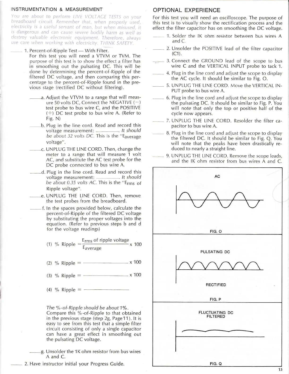
4. Plug in
the Iine cord
and adjust the scope
to display
the AC
cycle.
It
should be
similar to
Fig.
O.
5"
UNPLUC
THE
LINE
CORD.
Move
the VERTICAL lN-
PUT probe
to bus
wire
A.
6.
Plug
in the line
cord and adjust the scope
to
display
the
pulsaiing
DC. It
should be similar
to
Fig. P.
You
w,ill note
that only the top
or
positive
half of
the
cycle now appears.
7.
UNPLUC
THE
LINE
CORD. R.esolder
the filter ca-
pacitor
to bus wire A.
8. PIug in
the line cord
ar.rd adjust the
scope to display
the filtered DC. It
should be similar
to
Fig.
Q.
You
will
note that
the
peaks
have
been drasticaliy re-
duced to nearly
a straight line.
9. UNPLUC THE
LINE
CORD.
Remove
the scope leads,
and the IK
ohm
resistor
from
bus rvires A and
C.
(2)
%
Ripple
:
(3)
%
Ripple
:
Eaverage
x
100
x
100
x
100
(4)
%
Ripple
:
T he'k -of-Ri pple
should be about 1
o/o
.
Compare
this
%-of-R.ipple
to that
obtained
in
the
previous
stage
(step
29, Page11
).
lt is
easy to
see
from
this test that a simple filter
circuit
consisting of only
a single capacitor
can have
a
great
effect
in
smoothing
out
the
pulsating
DC voltage.
--9.
Unsolder the
1K
ohm resistor from bus wires
A
and C.
2. Have
instructor initial
your
Progress
Cuide.
AC
I
FIG.
O
FLUCTUATING
DC
FILTERED
PULSATING
DC
FIG.
Q
13
 Loading...