―13―
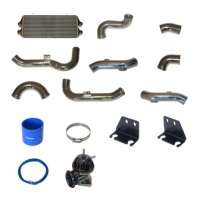
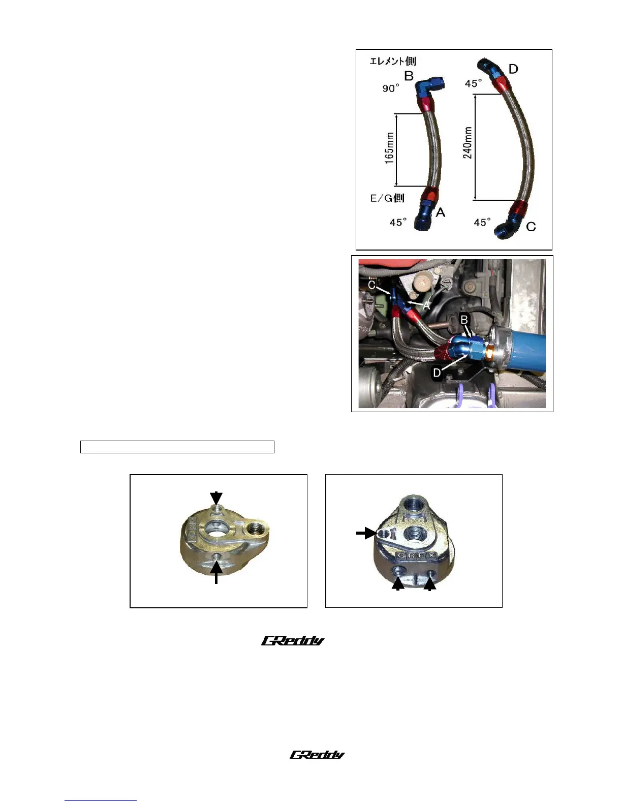
(6) Connect oil hoses #27 (A) & #28 (B).
・ Oil line hose A goes between the center unions.
Where the 90 degree fitting is on the filter side,
and the 45 degree fitting on the engine side.
・ Oil line hose B goes between the side unions.
Where the 45 degree fittings are on each side.
※ Use the corrugated tube (#31) to cover any part of
the oil lines that might make contact with any part
of the chassis or the other oil line.
※ Refer to the Images to reference where each end
of the hoses should go.
〈Parts used: 27, 28,31〉
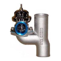
Optional Sensor Installation Instructions
Engine Block side Oil filter side
・ Sections A、B、E (1/8PT)・・・able to measure oil temperature and oil pressure.
・ Section C (1/8PT) ・・・ The electrical type warning meter temperature
sensor fits here.
・ Section D (M14×P1.5) ・・・Mechanical type temperature sensor fits here.
A
AA
A
B
BB
B
E
EE
E
D
DD
D
C
CC
C
 Loading...