8
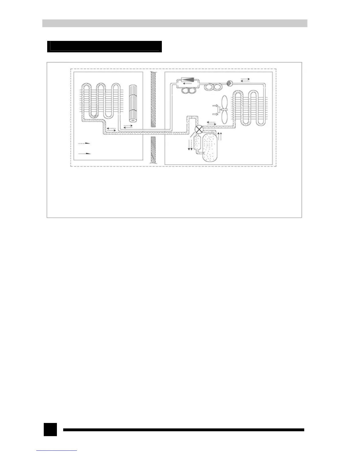
5. System schematic diagram
Evaporator Cross flow fan
Refrigerant flowing direction
when heating
Refrigerant flowing direction
when cooling
One-way valve Filter
Main capillary
Auxiliary capillary
Axial flow fan
Condenser
Electromagnetic
four-way valve
Gas liquid separator Compressor
When powered on, indoor and outdoor unit will start to run. When the system operates in cool mode, the compressor sucks low-temperature,
low-pressure refrigerant gas from indoor evaporator, compresses it into high-temperature, high-pressure refrigerant gas and discharges it into outdoor
heat exchanger. With the help of axial flow fan, the gas transfers its latent heat into outdoor air and becomes refrigerant liquid. The liquid is throttled
by throttling device and changes into low-temperature and low-pressure liquid and then flows into indoor heat exchanger. With the help of indoor unit
cross flow fan, the liquid becomes low-pressure refrigerant gas after it exchanges heat with indoor air. Such cycles are repeated continuously to
achieve cooling effect. When the system operates in heat mode, the four-way valve changes its way and the refrigerant flows into the reversed cycle
of the cool mode. The refrigerant discharges its latent heat indoor through the heat exchanger, and sucks heat from outdoor heat exchanger and forms
the heat pump cycle to achieve heating effect.