GREE ELECTRIC APPLIANCES, INC.OF ZHUHAI Page 2
:
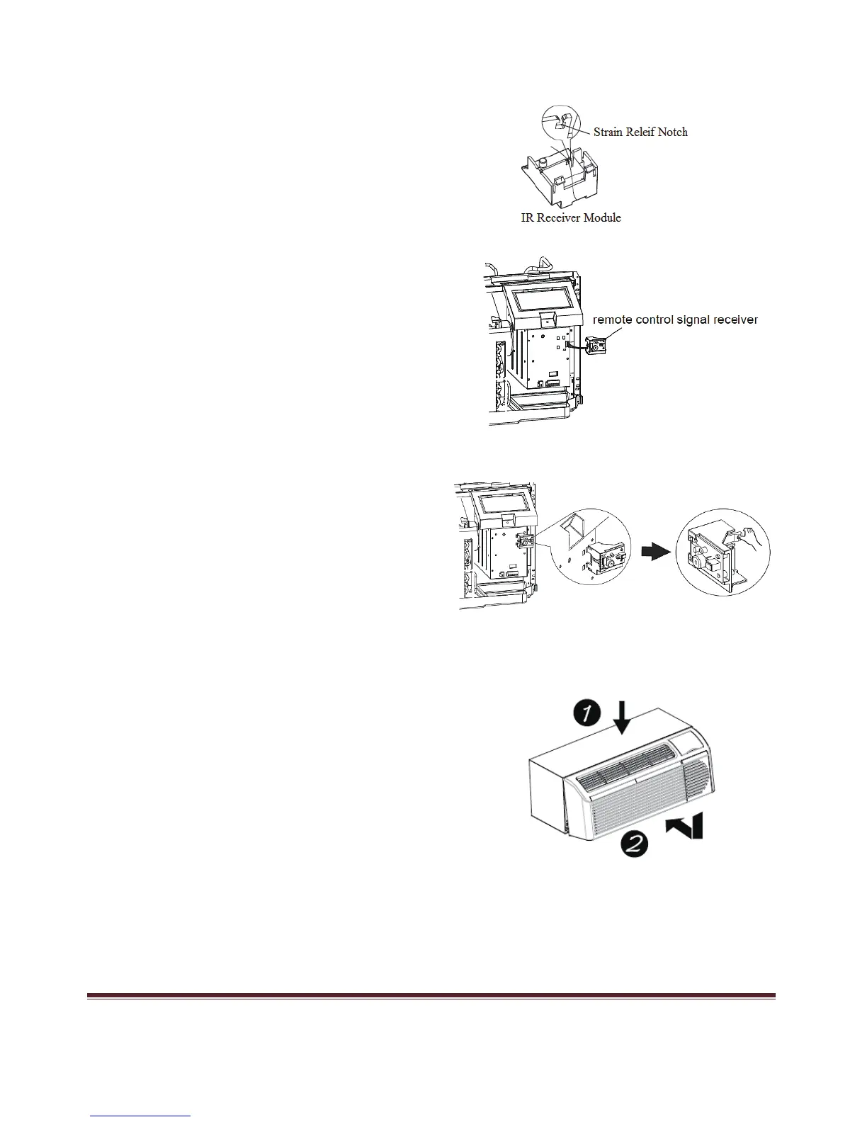
back of the module.
on the electrical control box.
the three (3) mounting legs into the corresponding
holes on the electrical control box. Verify the
electrical wires remain in strain relief notch.
Step 6: Replace front panel on ETAC unit by lining up tabs on
Step 7: Installation is complete. Plug in unit and apply electrical power to ETAC. IR Remote
Control System is ready for use. (No additional configuration or setup is required)
until it snaps into place (2).
Step 3: Place IR Receiver wires in the strain relief notch on the
Step 4: Insert electrical connector into mating connector
Step 5: Attached the IR Receiver module by inserting
top of the unit. (1). Then swing the front panel down and inward