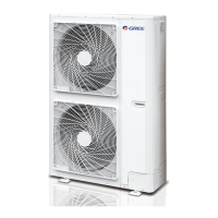
Do you have a question about the Gree GMV-100WL/C-T and is the answer not in the manual?
Lists various outdoor unit models with specifications including capacity, power supply, and refrigerant type.
Explains the model naming convention for outdoor units, detailing the meaning of each character in the code.
Highlights key system features such as high energy efficiency, advanced CAN bus communication, and long connection pipe capability.
Presents detailed technical specifications for various unit models, including cooling/heating capacity, noise levels, dimensions, and power requirements.
Defines the operational temperature limits for cooling and heating modes, specifying the outdoor ambient temperature range.
Details correction factors for indoor and outdoor temperatures, and pipe length/height differences impacting system capacity.
Describes the fundamental working principles of the VRF system, outlining the function of key components in the refrigeration cycle.
Explains the unit control schematic and the interpretation of signals for system operation and monitoring.
Introduces the automatic central management system for air conditioners via internet or local area network for efficient operation.
Details the Gree Commissioning Tool Kits software for comprehensive monitoring, control, and commissioning of VRF systems.
Covers essential preparation steps, safety notices, installation key points, and potential problems during VRF system installation.
Specifies requirements for installation materials, including refrigerant piping, condensate water pipes, insulation, and communication/power cables.
Provides procedures, cautions, and preparation steps for performing unit debugging after installation or component replacement.
Lists display codes and their corresponding malfunctions for wired controllers and indicators on the outdoor unit's main board.
Offers diagnostic flowcharts for common system issues, including communication malfunctions, high/low pressure protection, and temperature issues.
Illustrates the control logical relationship among unit components and introduces main electric parts like filter plates and IPM modules.
Identifies key system components and provides step-by-step instructions for their safe removal and replacement procedures.
| Refrigerant Type | R410A |
|---|---|
| Outdoor Unit Type | GMV-100WL/C-T |
| Indoor Unit Type | Multiple options available |
| Type | Multi VRF System |
| Noise Level (Indoor Unit) | Varies depending on indoor unit type |
| Indoor Unit Dimensions (HxWxD) | Varies depending on indoor unit type |
| Indoor Unit Weight | Varies depending on indoor unit type |


