GREE DC Inverter Multi VRF System II Service Manual
83
GMV-141WL/C-T
When debugging is finished, press SW1 on the master unit for 5s and unit will be ready for function
setting. Default display of outdoor unit’s main board is as below, then press SW1 button(Ʒ) and SW2
button() on the master unit to switch function codes of LED to select relevant functions.
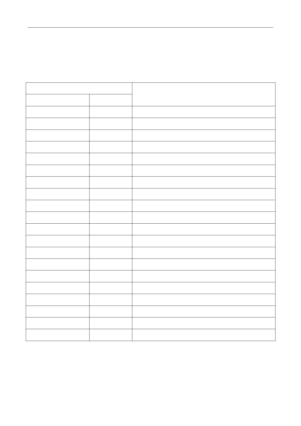
LED
Function
Function code Display
A7 Blink Quiet mode setting
A6 Blink Heat pump function setting
qd Blink ODU target of subcooling
n1 Blink Defrosting period K 1 setting
n2 Blink Setting of upper limit of IDU/ODU capacity distribution ratio
n3 Blink Compulsory defrosting
n4 Blink Limit setting for max. capacity/output capacity
n5 Blink IDU number offset setting
nH Blink Adjusting target of high pressure
nL Blink Adjusting target of low pressure
nU Blink Clearing IDU remote shield
q7 Blink Temperature in Fahrenheit
q8 Blink Corrective value b for low discharge temperature
A2 Blink Refrigerant recovery
A8 Blink Vacuum pump mode
q9 Blink Defrosting mode setting
qF Blink compulsory cooling
qL Blink Static Pressure Function
qn Blink Solar on-grid setting
qU Blink Grid voltage configuration
Note˖A6˄Heat pump function setting˅ǃn1˄Defrosting period K 1 setting˅ǃn3˄compulsory
defrosting˅ǃnH˄Adjusting target of high pressure˅ǃq9˄Defrosting mode setting˅ etc are unavailable
for Cooling only units.
Default display is “A7”, then press SW1 button(▲) and SW2 button(▼) on the master unit to switch
function codes of LED to select relevant functions. After selecting relevant functions, press SW3 to
confirm and start setting this function. Main board of outdoor unit will display as below:
 Loading...