GMV DC Inverter VRF
59
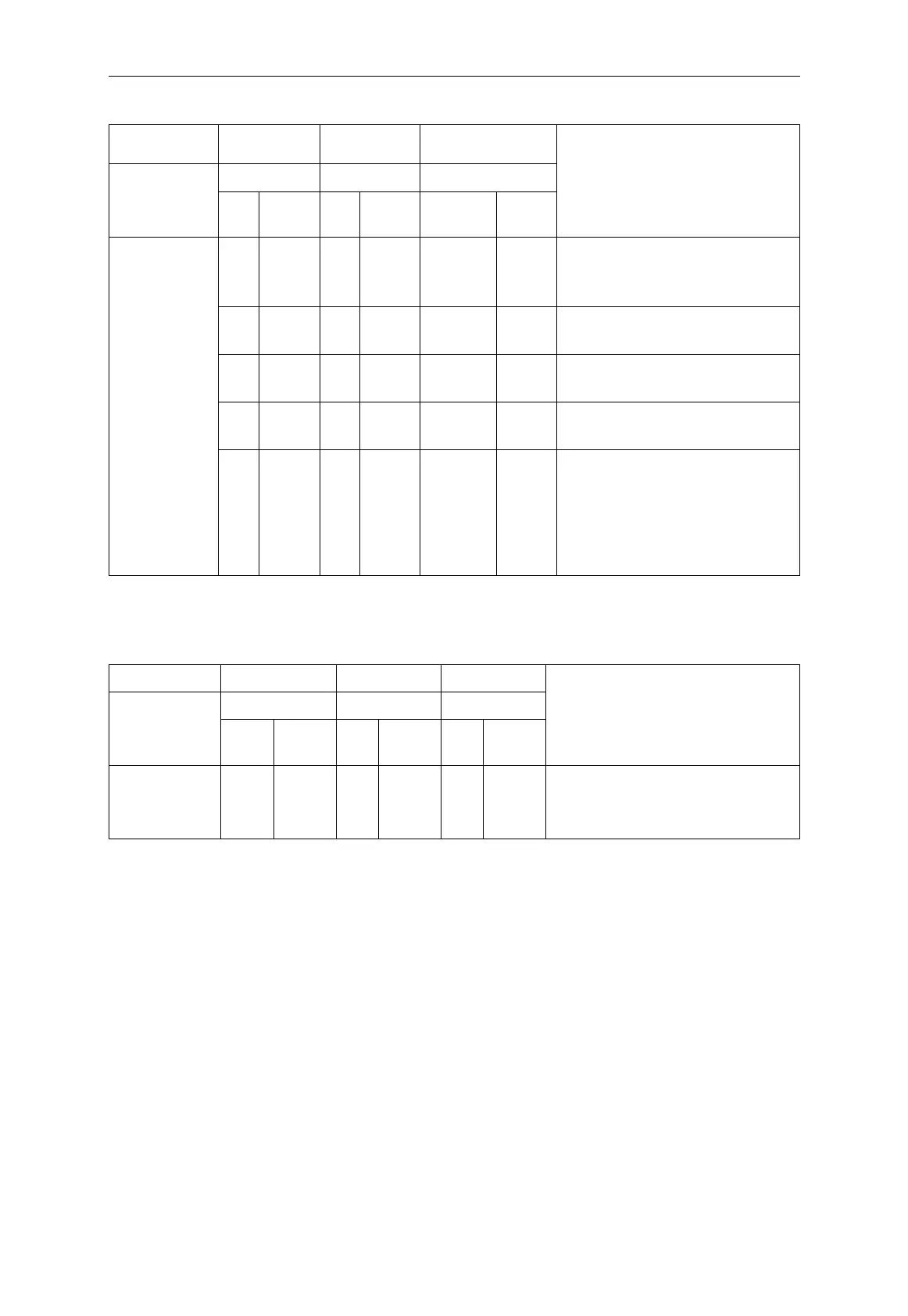
B If heating mode is selected, relevant display is as below:
Debugging is enabled in heating mode
(debugging mode, auto-selected by
system).
Error occurs during debugging in
heating mode.
Error of other modules occurs during
debugging in heating mode.
Outdoor pipeline and valves are not
normal.
System detects error in indoor
pipeline. XXXX is the project no. of the
faulted IDU. 3s later, error code U8 is
displayed. For example, IDU no. 100
has U8 error, then LED3 displays like
this: 01 (2s later) 00 (2s later) U8, and
repeat again.
Step 18:
if there’s no error during operation for about 40min, system will automatically
confirm that debugging is finished and then stop. System resumes standby condition and
displays as below:
Debugging is finished. System is on
standby condition. LED1 displays
module address. LED2 and LED3
display “OF”.
Step 19:
after debugging is finished, some functions can be set up according to project’s
actual needs. For specific details, please refer to System Functions Setup. If no special
requirements, skip this step.
Step 20:
deliver the product to user and inform user about usage precautions.
 Loading...